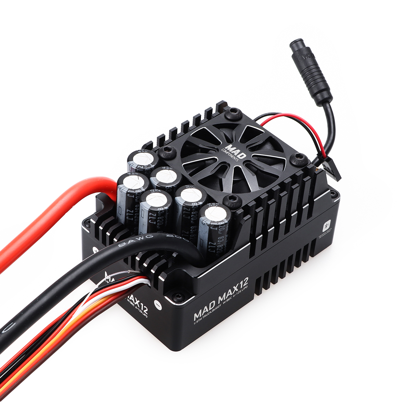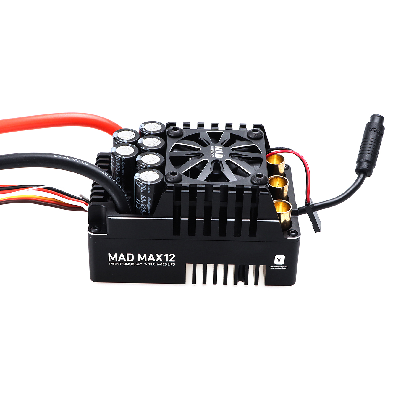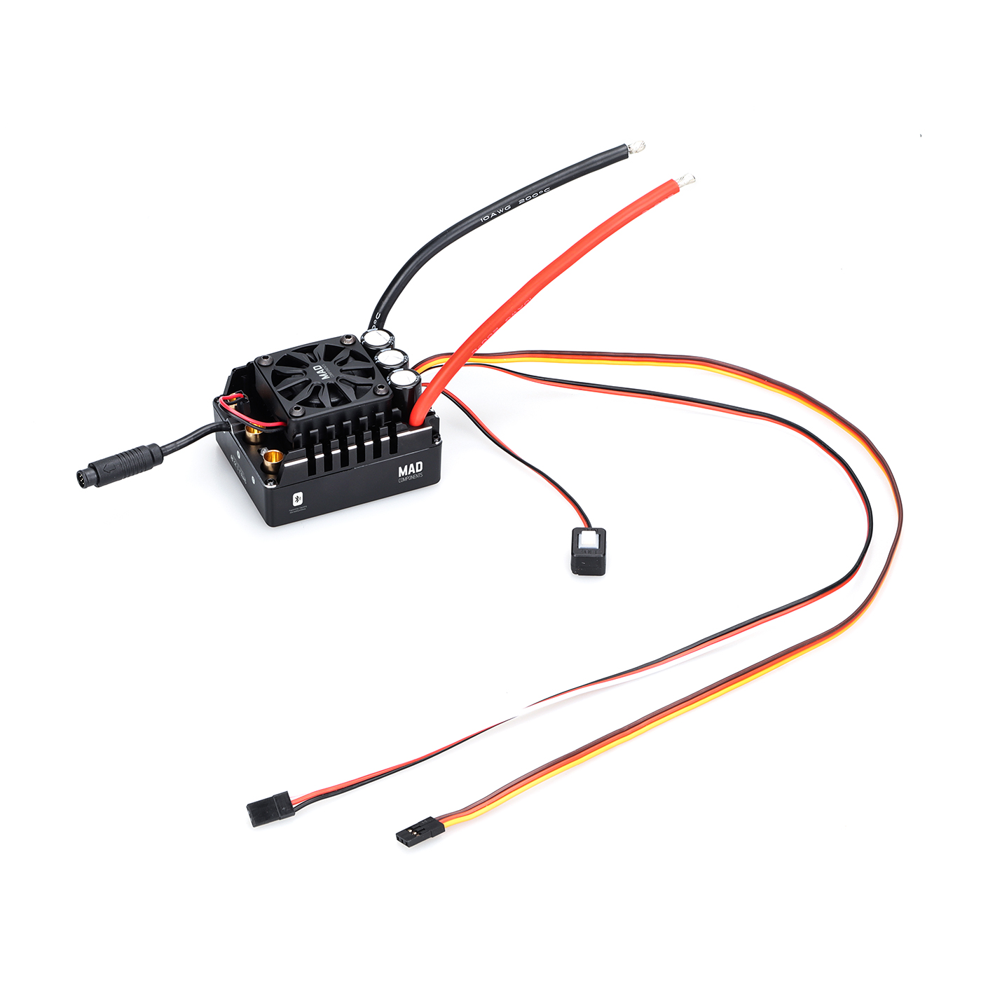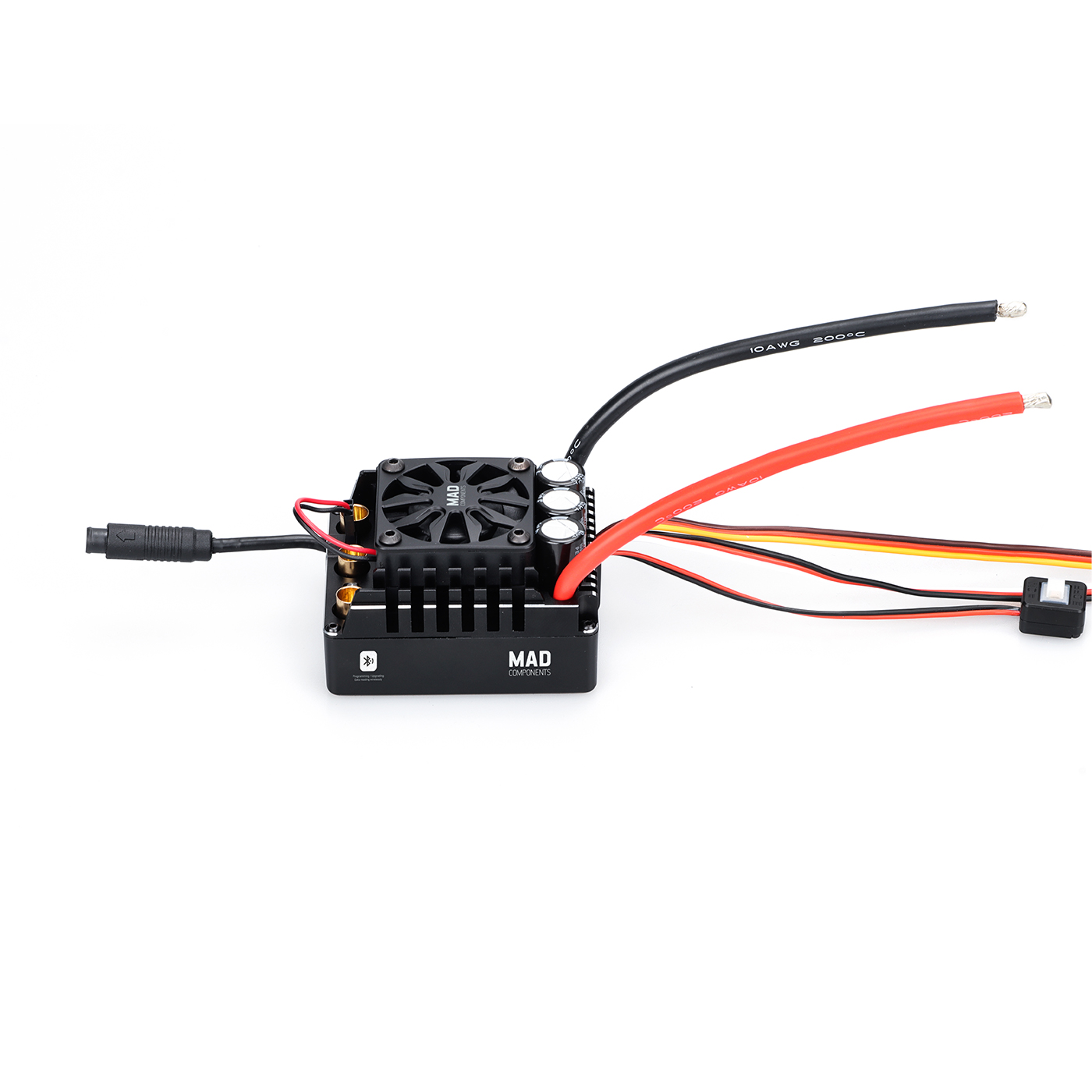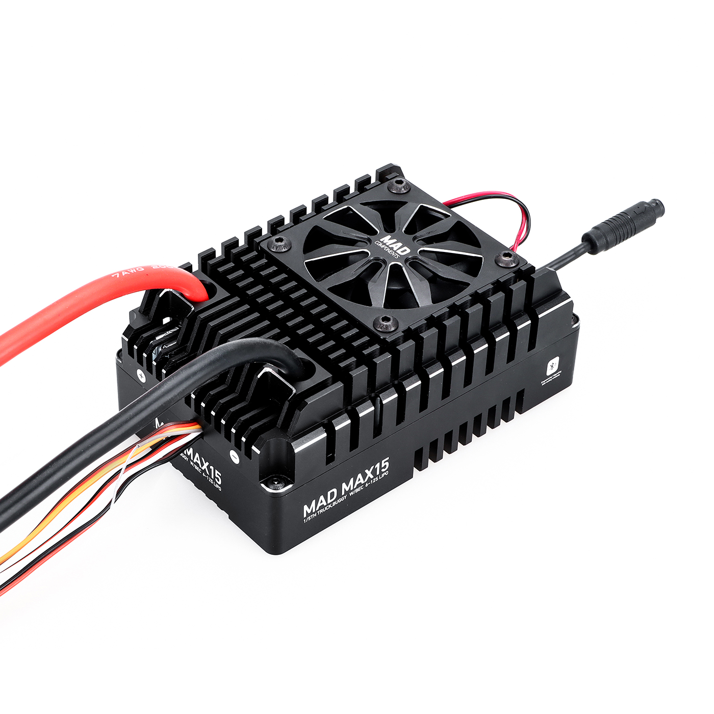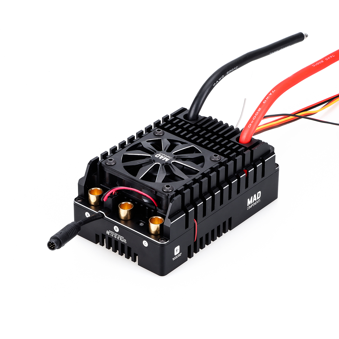


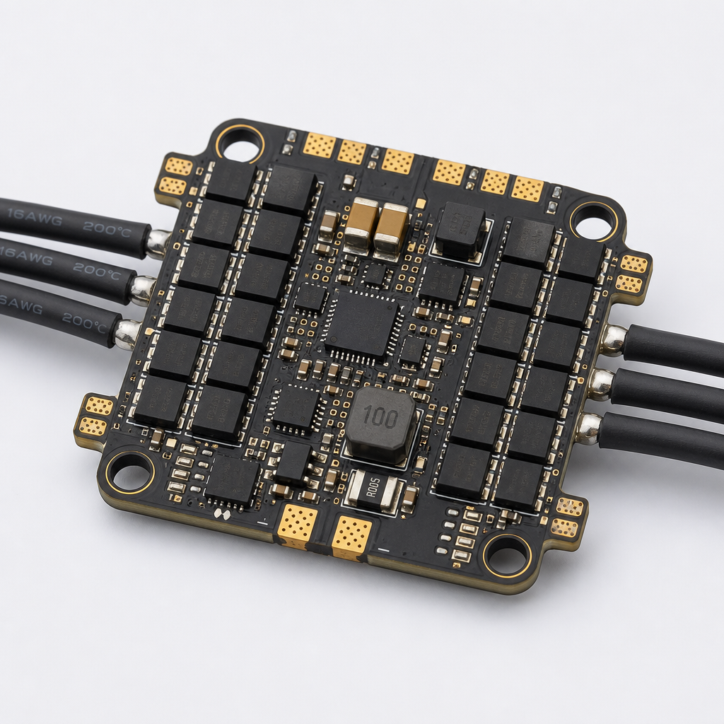
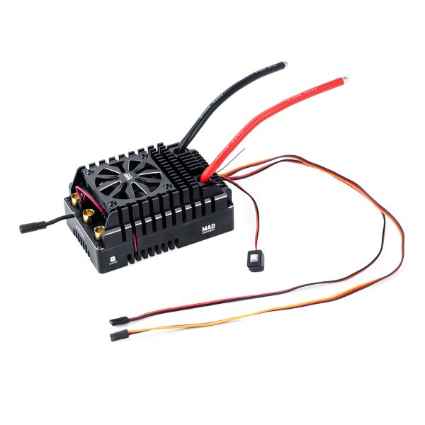
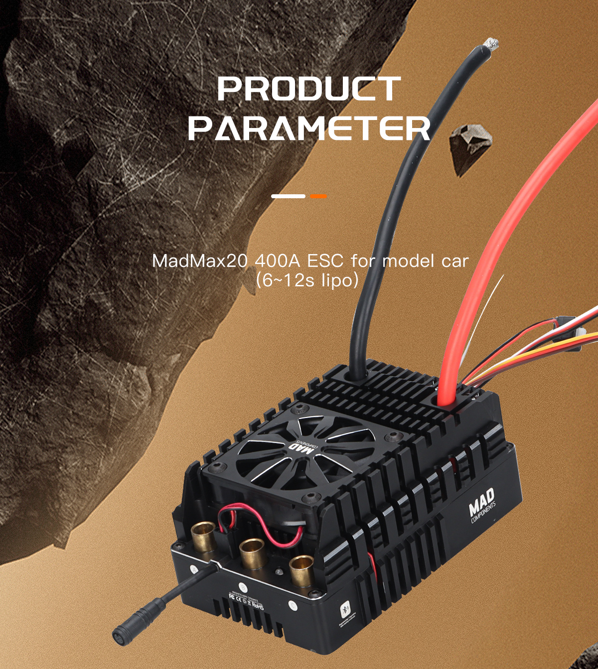
MAX20 400A HV 6–12S Sensored ESC for matched RC car ESC applications
MAX20 400A HV 6–12S Sensored ESC is identified by its listed model, size or electrical class and product type. Confirm the exact configuration, mounting interface and current manufacturer documentation before ordering.
For a propeller, match diameter, pitch, rotation, hub and clearance to the aircraft and motor. For an ESC, match cell count, motor, connector, sensor interface, cooling and programming requirements to the RC vehicle. Do not infer missing thrust, RPM, current duration, KV, BEC, weight, certification or payload limits from the product name or images.
This product is not a universal replacement. Verify the selected option, mechanical fit, wiring polarity and operating limits before commissioning, and perform restrained testing before normal operation.
For related selection, review the AM110 power-system kit, compare the MAX-series ESC range, and browse the propeller category.
MAX20 400A HV 6–12S Sensored ESC FAQ
What should be confirmed before ordering?
Confirm the exact model, interface, installation direction, included parts and current manufacturer documentation.
Can the size or current label guarantee performance?
No. Actual performance depends on the matched system, environment, cooling and validated testing.
Is this a universal replacement?
No. Verify compatibility with the specific aircraft, motor, ESC, battery or RC vehicle before use.
Especificaciones del producto:
| Artículo | Descripción | |
| Actual | 400A Continuous Current | El control de la corriente es similar a la limitación de corriente onda por onda, que limitar eficazmente la corriente máxima para evitar daños en el motor. |
| Fuente de alimentación | 6~12S LiPo | Cuando se utiliza una fuente de alimentación de corriente continua en lugar de una alimentación exclusivamente por batería, su descarga y hay que tener en cuenta la capacidad de recuperación de la alimentación eléctrica. Si la fuente de alimentación la capacidad es limitada, los parámetros de funcionamiento (como la aceleración y las opciones de frenado correspondientes, etc.) se puede modular adecuadamente. |
| Motor recomendado | Control de onda cuadrada con sensor o sin sensor de motores sin escobillas |
|
| Velocidad del motor | Cuando el número de pares de polos es 1, la corriente eléctrica La velocidad es exactamente igual a la velocidad mecánica. Otros: Velocidad eléctrica = Velocidad mecánica × Número de pares de polos = valor de KV × tensión del bus × número de pares de polos Nota: velocidad máxima en modo eléctrico: 240 000 rpm. |
La velocidad del motor es muy alta cuando está al ralentí. Ten cuidado. |
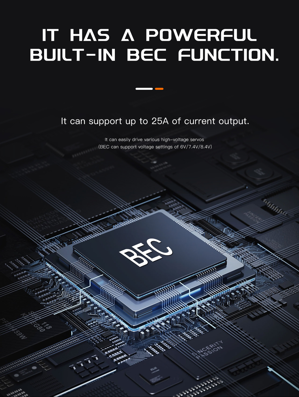
| BEC | Tensión: 6,0 V/7,4 V/8,4 V, Se puede activar a través de la aplicación móvil. Current: 10A continuously, 25A short-term |
|
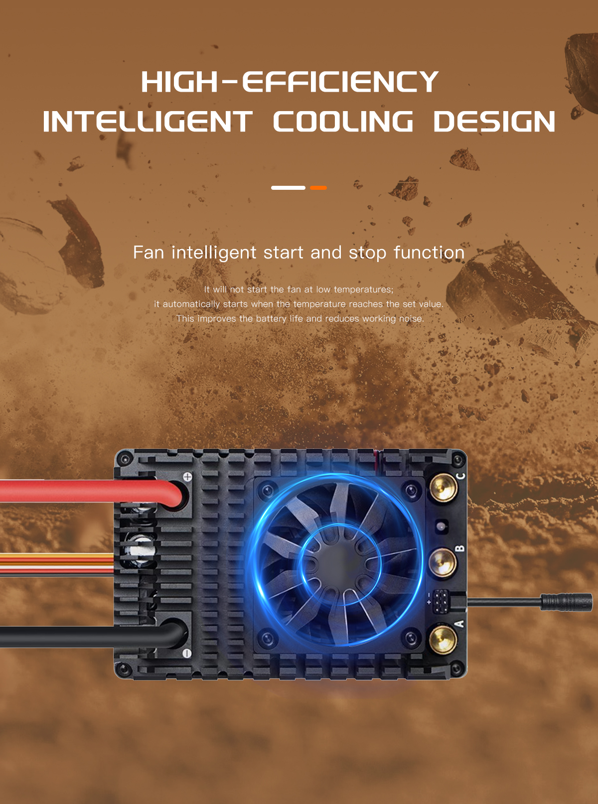
| Aficionado | Temperatura > 55 ℃: se activa la alimentación eléctrica del ventilador. Si la temperatura es inferior a 50 ℃, se desconecta la alimentación eléctrica del ventilador. Cuando se produce una anomalía importante en la corriente, el controlador corta la alimentación del ventilador |
1. El ventilador alimentado por el BEC 2. Cuando se produce una corriente de cortocircuito en el ventilador, Se cortará el suministro eléctrico. Se restablecerá el suministro en 1 segundo. |
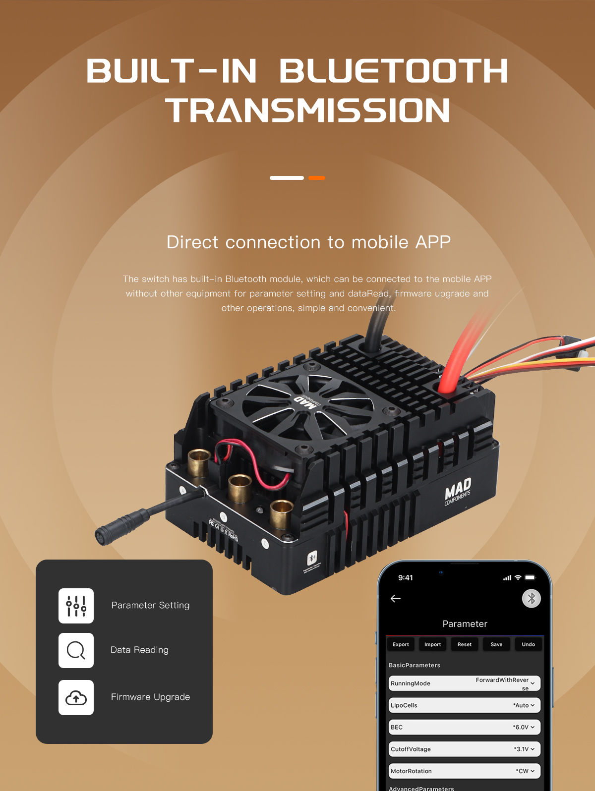
| Bluetooth | 1. Todos los parámetros del ESC se pueden ajustar mediante la aplicación móvil 2. El firmware del ESC se puede actualizar mediante la aplicación móvil. 3. Observación de los datos de funcionamiento del motor: registro de datos y datos en tiempo real. |
|
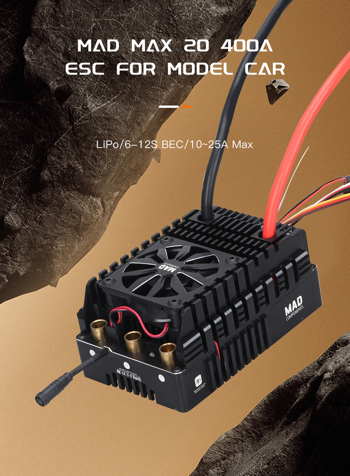
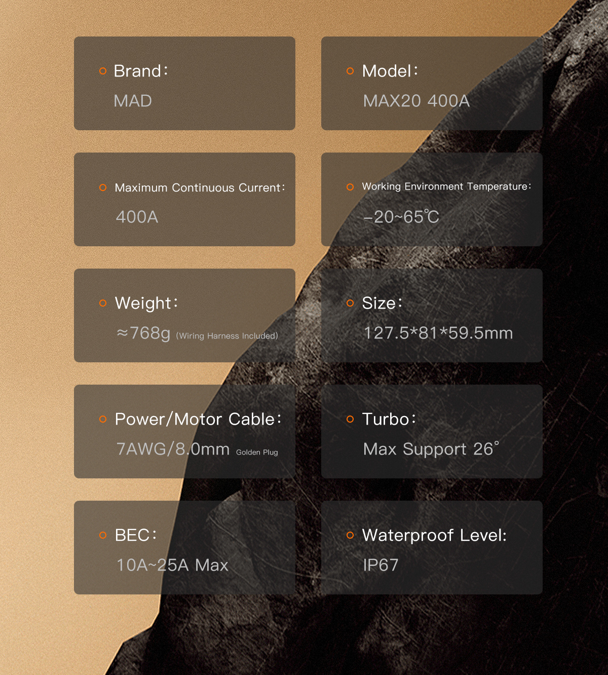
| Dimensión | 127.50(L)*81.00(W)*59.50(H)mm / ≈768g (with wire) |
Características:
2.1 Esquema de conmutación rigurosamente comprobado, conmutación fluida incluso en circuitos no inductivos.
2.2 La tecnología de rueda libre activa puede reducir el calentamiento del MOS y, al mismo tiempo, evitar picos de corriente excesivos.
2.3 La limitación de corriente en cada ciclo PWM reduce el impacto de la corriente de pulso en el motor.
2.4 La disipación inteligente del calor garantiza que el ventilador funcione de forma silenciosa a bajas temperaturas.
2.5 Conexiones Bluetooth integradas con una aplicación móvil para la gestión del hardware y la configuración de parámetros.
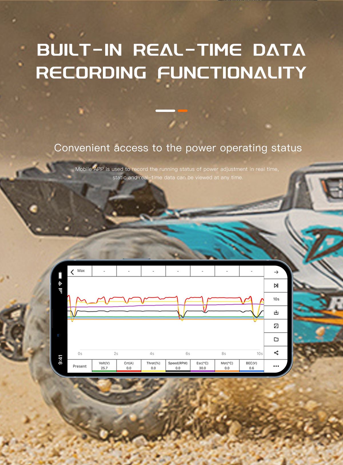
2.6 Interfaz de visualización de datos de la aplicación móvil para consultar los datos registrados por el ESC (datos estáticos) y los datos de depuración en tiempo real.
2.7 El circuito de conversión de corriente continua de alta potencia confiere al BEC una gran capacidad de carga.
2.8 Protección completa: baja tensión, sobretensión, pérdida de aceleración, frenado anómalo, sobrecalentamiento, etc.
2.9 Se ofrece sincronización del turbo.
2.10 No hace falta comprar módulos adicionales, ya que dispones de un regulador de velocidad LISTO PARA USAR.
2.11 Compatible con el protocolo XC BUS, control en tiempo real del ESC y lectura de datos de funcionamiento a través del bus. Se puede utilizar para el control de robots u otros sistemas de control mediante programación automatizada.
Conexiones: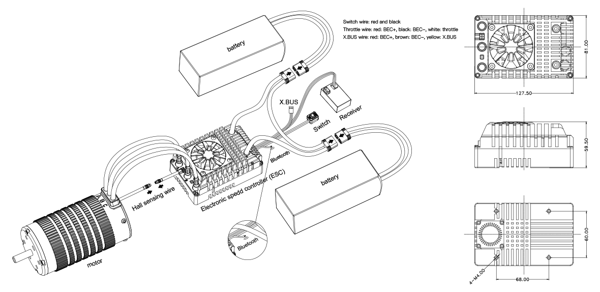
Precauciones:
- Por favor, no conectes los cables de entrada del ESC (DC+ y DC-) al revés. Una conexión inversa podría dañar el ESC.
Si el ESC resultara dañado en este caso, no se prestará el servicio de garantía correspondiente. - Si se utiliza un sensor Hall, asegúrate de comprobar los cables de fase del motor y el cableado del sensor Hall.
- En el caso de los motores sin sensores de temperatura, un funcionamiento prolongado a alta potencia puede provocar que se quemen.
- La estructura mecánica de algunos motores no soporta altas velocidades. Si se aumenta la velocidad a la fuerza, el motor podría sufrir daños.
- Si no se va a utilizar durante más de una hora, se recomienda desconectar los cables de alimentación del ESC.
- Si se ha realizado alguna modificación en el cable de conexión, comprueba minuciosamente el circuito antes de ponerlo en funcionamiento. Se recomienda abrir el acelerador poco a poco y comprobar que no haya ningún fallo antes de acelerarlo con normalidad.
Iniciar el proceso:
Pasos:
1. Comprueba si el circuito está abierto, si hay un cortocircuito o si hay un mal contacto.
2. Comprueba si el motor está atascado.
3. Enchufa el cable de alimentación.
4. Pulsa el botón de encendido.
Cuando oigas el tono de aviso de la batería (descrito en el apartado “Arranque normal” de la sección de avisos luminosos y acústicos), el arranque es normal. Si el acelerador funciona con normalidad, puedes
Acciona el acelerador como de costumbre.
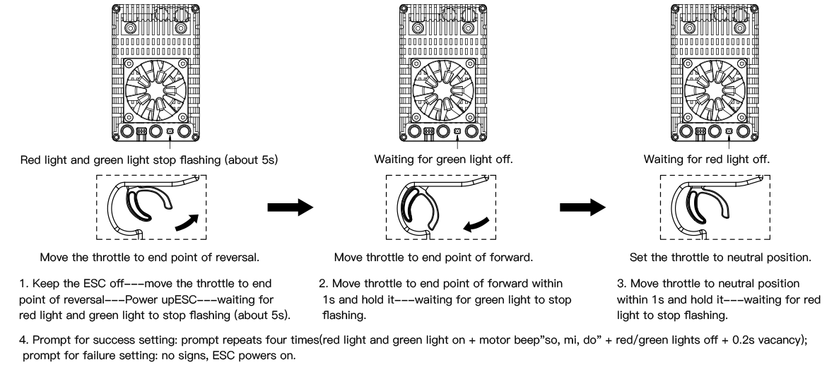
Configurar el rango del acelerador:
Bluetooth:
La regla para nombrar los dispositivos Bluetooth es “modelo aproximado” + “-” + “ID del código ESC”; por ejemplo, en “XC_E3-1C89”, “XC_E3” es el modelo aproximado y «1C-89» es el código hexadecimal.
ID de código del ESC. Aunque el usuario configure él mismo el nombre de Bluetooth, se mantiene el ID de código del ESC para evitar que haya dos dispositivos con el mismo nombre.
Elementos configurables:
| N.º de secuencia | Artículo | Descripción | Por defecto | |||
| 1 | Modo de funcionamiento | Marcha adelante con freno | Marcha adelante y atrás y freno | Marcha adelante con marcha atrás | Marcha adelante y atrás y freno | |
| 2 | LipoCells | Auto | 6 ~ 16S | Auto | ||
| 3 | Tensión del BEC | 6,0 V | 7,4 V | 8,4 V | 6 V | |
| 4 | Tensión de corte | Discapacitado | 2,9~3,6 V | 3,2 V | ||
| 5 | Rotación del motor | Forward | Reverse | Forward | ||
| 6 | Max.Brake Force | 0~100% | 60% | |||
| 7 | Max.Reverse Force | 0~100% | 25% | |||
| 8 | Punch | 0~12 level | 6 level | |||
| 9 | Drag Brake Force | 0~100% | 0% | |||
| 10 | Turbo Timing | 0~26 degree | 26 degree | |||
| 11 | Turbo Delay | 0~1S | 1s | |||
| 12 | Initial PWM | 1~10% | 5% | |||
| 13 | Motor Pole Pairs | 2~15% | 10% | |||
| 14 | Motor Pole Pairs | 1~64 | 2 | |||
| 15 | Communication BUS | X.BUS Protocol | X.BUS Protocol | |||
| 16 | X.BUS-ID | 0~15 | 0 | |||
1. Running Mode:
Option 1: Forward with brake
The vehicle can only move forward and has brake function. This is also commonly acceptable in races.
Option 2: Forward/Reverse and Brake
This option is known to be the “training” mode with “Forward/Reverse with Brake” function. The vehicle only brakes at the first time you push the throttle trigger to the
reverse/brake zone. If the motor stops when the throttle trigger return to the neutral zone and then re-push the trigger toreverse zone, the vehicle will reverse.if the motor
does not completely stop, then your vehicle won’t reverse but still brake, and you need to return the throttle trigger to the neutral zone and push it to reverse zone again.
This method is for preventing vehicle from being accidentally reversed.
Option 3: Forward and Reverse
When the throttle trigger is pushed from neutral to reverse point, the motor reverses. This mode is generally used in special vehicles.
2. Lipo Cells:
Set the correct value according to the actual number of Lipo batteries used. The default is automatically calculated.
3. Low Voltage Cut-Off:
This function is mainly to prevent excessive discharge of lithium batteries causing damage. The ESC monitors the battery voltage at all times, and once the voltage falls
below the set threshold, the power output is reduced and the power output is completely cut off after a few seconds,and generates a 10% braking force. For NIMH
batteries, it is recommended to set this parameter to “Disabled”.
4. Motor Rotation:
Setting the rotation of the motor. Due to some differences in the drivetrains on different car kits, it is possible that the car will go in the opposite direction upon full throttle.
In the event that this happens, you can set the“motor rotation direction” to the opposite direction; “CW” or “CCW”.
5. BEC Voltage:
BEC voltage supports 6V/7.4V/8.4V. Generally, 6.0V is suitable for standard servos, while 7.4V/8.4V is suitable for high-voltage servos. Please set according to the servo specifications.
WARNING! Do not set the BEC voltage above the maximum operating voltage of the servo, as this may damage the servo or even the ESC.
6. Max. Brake Force:
This ESC provides proportional braking function; the braking effect is decided by the position of the throttle trigger. It sets the percentage of available brakingpower when full brake is
applied. Large amount will shorten the braking time but it may damage your pinion and spur gear.
7. Max. Reverse Force:
Refers to the reversing speed. Selecting different parameter values can produce different reversing speed. It is recommended to use a smaller reversing speed to avoid
errors caused by reversing too fast.
8. Punch:
Set in 1-9 stages, the higher the set value, the faster the acceleration. Kindly consider according to the site, tire grip characteristics vehicleconfiguration etc. An aggressive
setting may cause tire slippage, excessive starting current and adverse effects on the electronics performance adversely.
9. Drag Brake Force:
Refers to the brake force generated by the motor when the throttle trigger returns to neutral position. Choose the appropriate value according to the type of vehicle, configuration, site, etc.
10. Turbo Timing:
The Turbo timing can additionally increase the motor rpm.It will initiate at full throttle. It is usually used on a long straight road to release the maximum power of the motor. The higher
this value is, the more the rpm of the motor will increase, and the greater the running current will be, the higher the temperature of the motor and esc. Therefore, please set this value
reasonably.
11. Turbo delay:
It refers to the duration of continuous full throttle required to trigger Turbo. When the full throttle time reaches this set value, Turbo can be triggered to turn on.
12. Initial PWM:
Also called minimum starting force, it refers to the starting force acting on the motor at the initial position of the throttle. The required starting force can be set according to the tires and
site grip. If the venue is too slippery, set a smaller starting force to avoid slipping.
13. Motor Pole Pairs:
For setting pole pairs. Motor Rotation speed=Electrical Speed / Pole Pairs, To get the precise mechanical rotational speed, the pole pairs must be set correctly.
14. Communication BUS:
FUTABA_T4PM & FS sensor-to-sensor data transmission:These two modes of data transmission are available, voltage, temperature and motor speed etc can be viewed
on RC. XC. BUS Controls the throttle of ESC in the form of programming, or dynamically adjusts the motion parameters, reads the operation parameters of ESC, etc. It can be
used in automation or robot situations. For specific content of the protocol, please refer to the XC.BUS Control Protocol.
15. XC.BUS-ID:
This item will take effect if XC.BUS is selected in item 14. XC.BUS can control up to 16 ESCs.
Recover factory parameters:
How to restore Bluetooth to factory settings:
If the Bluetooth password is lost or if you need to forcibly enter Boot, please follow the instruction:
Step 1: Connect ESC wire(the white wire) to BEC+(red wire)
Step 2: Turn on ESC
Step 3: Disconnect from BEC when green light off and red light on
Step4. Remove short circuiting
When boot activated, the status of Bluetooth will restore to factory value(password will be restored to 1234, and the name will be restored to the factory state), then restart ESC,
If there is a hardware error, Boot can be activated in this way to upgrade hardware.
How to restore parameters to factory settings:
If you want to restore the parameters to factory settings, just click the default button on the APP parameter page.
LED status & beep instructions:
| Artículo | Type description | Light cue | Sound cue | Remark | |
| Basic information |
Throttle not zeroed | Red light flashes quickly | Long tone “beep” | Red light flashes quickly | |
| Throttle signal lost | Red light flashes slowly | Long tone “beep” | In cycle of 2s | ||
| Voltage detection | Low voltage protection | (Redx1 Greenx2) … | Long tone “beep”x1, Short tone “beep”x2 |
Check the input voltage or setting of number of cells if no “beep” before MOSFET detecting. |
|
| Over voltage protection | (Redx1 Greenx3) … | Nil | Voltage is too high, check whether the voltage is over the withstand value of ESC |
||
| The MOS temperature is too high, operating temp. > 125 ℃ / startup temp. > 110 ℃ |
(Redx1 Greenx4) … | Long tone beepx1, short tone beepx4 |
The temperature of MOS is too high. ESC can resume normal operation when the temperature drops below 100 degrees Celsius |
||
| The capacitor temperature is too high, operating temp. > 105 ℃ / startup temp. > 100 ℃ |
(Redx1 Greenx5) … | Long tone beepx1, short tone beepx5 |
The temperature of capacitor is too high. ESC can resume normal operation when the temperature drops below 100 degrees Celsius |
||
| Throttle parameters | Abnormal throttle parameters | (Redx1 Greenx7) … | Long tone beepx1, short tone beepx7 |
If there is still an abnormal promp when positioming throttle to neutral point, throttle calibration process needs to be initiated. |
|
| Hall sensing abnormality | Hall output logic abnormality | (Redx1 Greenx8) … | Long tone beepx1, short tone beepx8 |
Re-plug Hall wire. If the abnormality persists, it may be a problem with the internal Hall of the motor, and the Hall wire needs to be unplugged. |
|
| Throttle calibration prompt | Calibrate low range | (Red Green) … | Nil | If the calibration process is irregular or unsuccessful, the ESC will exit the calibration process and enter the normal Startup process. |
|
| Calibrate high range | (Green) … | ||||
| Calibrate neutral throttle | (Red) … | ||||
| Calibration success | (Red Green) x4 | (so-mi-do) x4 | |||
| Normal operation | All normal and no action to throttle | (Green) … | Nil | ||
| Throttle operation | Normal | The greater the accelerator, the faster the green light flashes |
|||
| Turbo timing is on | Green light remains on | ||||
| Braking | Red light is on | Nil | Red light off when release brake | ||
| Boot | Entering boot forcibly | Nil | Follow the process of Bluettoth factory reset | ||
| Boot in progress | Green light: On 2s&Off 2s | Nil | The duration of the red light on = the time of the flash operation |
||
| Red light remains flashing | |||||
| Normal startup | Prompt for the number of battery cells after normal startup |
Quinary prompt light signal, long tone with red light on, short tone with green light on |
do, mi, so + quinary prompt sound |
do, mi, so: prefix of quinary number Quinary definition Long tone = 5 cells, short tone = 1 cell Example: 8-cell lithium battery prompt sound do, ri, mi + long tone x1 + short tone x3 |
|
| Fault warning | MOS abnormality self-test | MOS open circuit | (Redx2) … | Nil | Unplug motor wire. If there are still abnormalities, ESC needs to be sent for inspection |
| MOS short circuit | (Redx2 Greenx1) … | Nil | |||
| Abnormal sampling circuit of current | (Redx2 Greenx2) … | Nil | |||
*Notes:
1. Red light matches long time. Green light matches short tone.
2. For saving power, all “beeps” last for 5mins; if all faults are recovered, it takes effect again in next 5 mins.
3. Ellipsis”…” in light cue represents the repetition of previous action.