


High Voltage ESC Wiring Precharge: Steps Before Power-Up
Why an 800 V connector arcs on contact, how to size the precharge resistor, and the six-gate checklist we run before an HV ESC sees pack voltage.
TL;DR
- High voltage ESC wiring precharge exists because a pack does not switch on at the connector: it charges the ESC’s input capacitance through whatever resistance is already in the loop, and that is a few milliohms. The precharge resistor inserts a known resistance first, so the pack delivers controlled current instead of a near short.
- Size the resistor from two numbers. Peak current is bus voltage divided by resistance; the wait is about five time constants of R × C. A 400 V bus with 1,000 µF wants 50–100 Ω and 0.5 s, a 600 V bus 100–200 Ω and 1.5 s, an 800 V bus 200–400 Ω and up to 4 s.
- Wiring geometry decides whether the precharge still works inside the airframe: 8 mm of air clearance and 12.5 mm of creepage on an 800 V bus, insulation resistance above 20 MΩ, and a logged rise that reaches 95% of pack voltage inside the designed window.
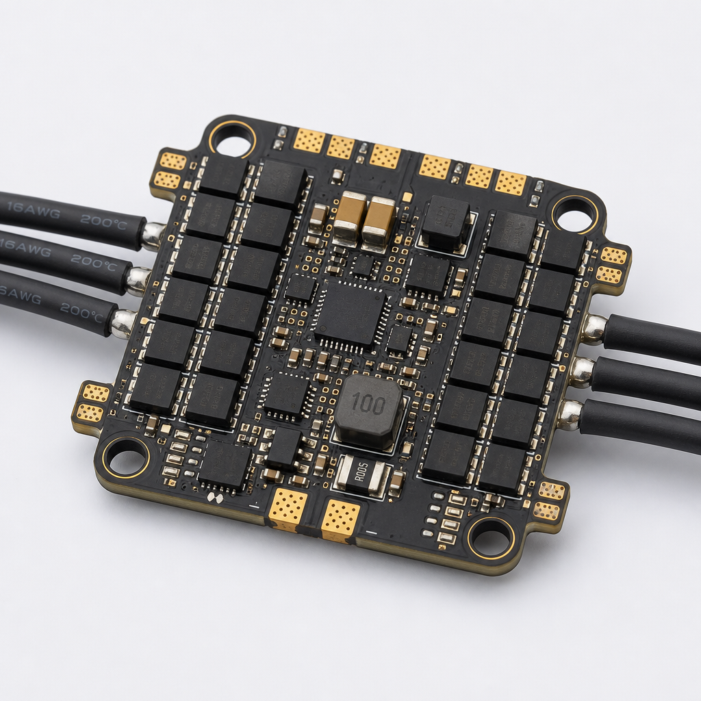
High voltage ESC wiring precharge is the ninety-second sequence that stands between a healthy pack and a pitted connector. What follows is the physics of the arc, resistor sizing for 400 V, 600 V and 800 V buses, connector and spacing rules, the six gates we run before power-up, and the bench tests that prove the circuit works. 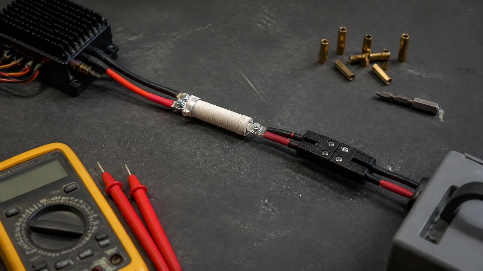 A 1,000 µF class bus charged through a 250 Ω wirewound resistor on an 800 V bench setup: ESC on the left, pack on the right, and the resistor plus anti-spark connector forming the only path between them until the bypass closes.
Why high voltage turns a connection into an event
Arcing at the connector is a capacitance problem, not a connector-quality problem. Every ESC carries bulk capacitors across its DC input, typically 470 µF to 2,000 µF at 400–800 V, and that bank is empty on the bench. Mating the connector puts a discharged bank across a charged pack, so only loop resistance limits current. Three quantities make the event:
- Peak current. A 48 mΩ loop on an 800 V bus asks for 16,000 A by Ohm’s law. The pack cannot deliver that, but it delivers what its internal resistance allows for tens of microseconds: four figures in amps.
- Stored energy. ½CV². At 800 V and 2,000 µF that is 640 J released into the contact face and the dielectric in a few milliseconds.
- Arc sustain. Air breaks down near 3 kV/mm, so at 800 V a gap under about 0.3 mm can strike an arc, and a DC arc has no zero crossing to extinguish it. Contact metal vaporises, and the crater it leaves is where the next failure starts.
The practical reading: below about 100 V you can usually mate a connector by hand, and above 400 V you cannot. The connector is not being asked to carry steady current but to interrupt a charging transient, and almost none in this class is rated for that duty. If the class is not yet fixed, the trade-offs between the three are covered in our note on 400 V, 600 V and 800 V ESC classes. This article assumes the class is set and the question is how to connect it.
High voltage ESC wiring precharge: what the resistor protects
Precharge protects three components, and only one of them is the connector. It limits how fast the bus capacitance charges, so the contact face never sees a near-short, the capacitor dielectric is not shocked by a step, and the pack’s protection path is not asked to survive an event it was never sized for. The circuit is a resistor in parallel with the main contactor, wired so the pack reaches the ESC only through that resistor until the bus is nearly charged.
- Resistor path closed. Current is capped at bus voltage divided by resistance: an 800 V bus behind 250 Ω sees 3.2 A, not four figures.
- Bus rises on the RC curve. Voltage climbs with the time constant R × C until the bus is within a few percent of pack voltage.
- Contactor closes. The bypass shorts the resistor once the bus passes roughly 95% of pack voltage, and load current then flows through no added resistance.
- Resistor drops out. In a latching design it sits in the path only for the precharge interval, which is what keeps its power rating sane.
What each element tolerates is worth stating plainly:
- Connector contacts survive a few amps of make-current indefinitely and a few hundred amps of arc once. Precharge turns the make into the first case.
- Bulk capacitors are rated for a ripple and a dV/dt. A step charge stresses the dielectric and the internal bonds; a ramp stays inside the datasheet.
- Pack protection — BMS limit, fuse, contactor — is sized for motor current, not a capacitor short.
One clarification saves arguments on the bench: a resistor-equipped anti-spark connector is a precharge circuit, just a small one. The resistor inside an XT90-S or AS150 style shell is typically a 5–10 Ω, 1–2 W part — enough for a few hundred microfarads, not 2,000 µF at 800 V. If the body is warm after mating, it is doing more work than it was designed for.
Sizing a precharge resistor for 400 V, 600 V and 800 V packs
Size the resistor from the pack, not from catalogue habit: pick resistance so peak current stays inside what the connector and pack can take, then confirm the wait fits the mission sequence. Four equations do the work.
- Peak current: I = V / R, held under about 10 A for a 5 mm bullet, and well under the pack’s burst limit.
- Time constant: τ = R × C, with C the total input capacitance of every ESC on the bus, not one of them.
- Wait time: about 5τ to reach 99% of pack voltage; 3τ reaches 95%, the threshold most contactor logic uses.
- Pulse energy: E = ½CV², absorbed in one event. This, not the wattage on the label, is what destroys undersized parts.
Resistor wattage and duty cycle
Wattage is a separate decision. Continuous rating has to cover the duty cycle — a precharge every flight, ten flights a day, is a repetitive pulse load — while the surge rating covers one event with margin. A 100 W aluminium-clad wirewound with a stated 5 s surge capability is a reasonable default for the 800 V row; a 25 W ceramic part is not. Worked example: an 800 V pack with 1,500 µF and 300 Ω gives 2.7 A peak, τ = 0.45 s, a 2.3 s wait and 480 J per event. A 50 W part rated for 300 J of surge fails open on the fourth power-up, and the next precharge does nothing while the connector takes the inrush. 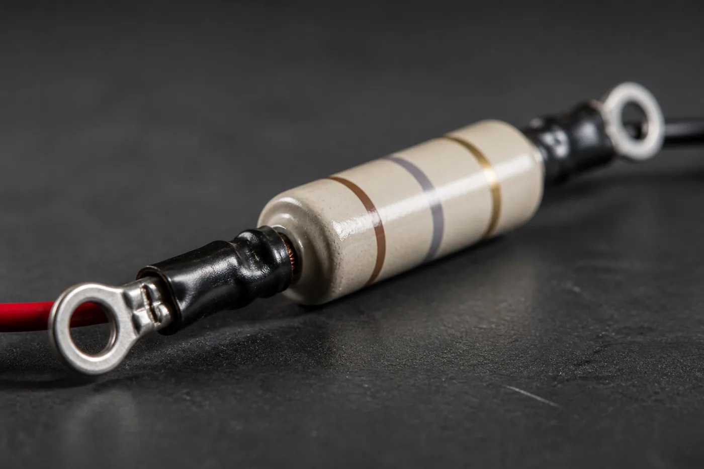 Crimped ring terminals under adhesive-lined heat-shrink: the crimp carries the current, the shrink only seals it. A soldered joint here wicks into the strand and creates a stiff point that cracks under vibration. Three installation rules follow from the same arithmetic:
- Mount it off the frame. The body can pass 200 °C on a long 800 V precharge; keep 20 mm of air around it and nothing flammable within 50 mm.
- Use the cold corner for the wait. Capacitance falls and ESR rises in the cold, so the circuit charges more slowly at −10 °C.
- Treat it as a service item, a removable harness part, not a soldered-in one.
Connector and cable rules above 100 V
Above 100 V the rules shift from adequate gauge and a firm fit to nothing may be mated under load, and no single fault may put pack voltage on the airframe. The list below is the short version we apply to every HV harness.
- No hot-plugging. Every HV connector is mated with the pack isolated or not mated at all. This includes the balance lead, which is the one people forget.
- Key them physically. Different shell size, keyway and colour for HV and LV; connectors that can be swapped by feel eventually will be.
- Derate for altitude. Breakdown voltage falls roughly 30% at 3,000 m for the same gap, so bench spacing is not altitude spacing.
- Crimp, do not solder, on stranded HV cable. Solder wicks up the strand and creates a rigid section where vibration fatigue starts. Crimp with a calibrated tool and pull-test the result.
- Support every 150 mm. No connector may carry cable weight; tie within 50 mm of each shell so the contact sees no bending load.
- Separate the DC pair from signal wiring. Twist the pack leads, and keep 50 mm from PWM, CAN and receiver wiring; an 800 V switching node couples into anything parallel.
Gauge follows current, and our continuous and burst current ratings note explains why the label number is not the number to size against. An 800 V class drive at 160 A continuous wants 6–8 AWG silicone cable rated above the bus voltage, with DC drop under 3% at rated current. Airworthiness rules differ by jurisdiction — the EASA drone rules and the FAA UAS portal are the two references most of our customers work to — but no regulator changes the physics of a 0.3 mm gap.
Insulation, clearance and creepage in practice
Clearance is the shortest path through air; creepage is the shortest path across the surface of the insulator. Both have to be designed, because potting compound does not fix a 2 mm gap between a phase post and a frame plate. The values below come from the IEC 60664-1 spacing tables for pollution degree 2 and material group IIIa, rounded up: bench values, not a certification claim.
Four failure modes account for most insulation problems in returned harnesses:
- A sharp point. Field concentrates at a burr or a solder spike, and the gap breaks down below the table value. Round or cover every termination.
- Carbon fibre inside the envelope. A 3 mm gap to a carbon plate is a 3 mm gap to ground.
- Condensation in a sealed bay. Pollution degree 2 assumes dry contamination; water changes the creepage number, not just the clearance.
- A cable tie pulling two potentials together. The tie is the creepage path. Stand the HV lead off with a spacer and check the gap with the harness installed and pulled.
Bonding belongs here too: enclosure, motor mounts and frame bonded to pack negative below 2.5 mΩ, so a single insulation fault trips protection instead of floating the airframe at 800 V.
A pre-power-up checklist
Run the six gates in order and treat each as pass or fail. A fail stops the sequence, and “we will check it after the first flight” is not a pass.
- Bond and inspect. Case bonded to pack negative, HV leads dressed away from sharp edges, no loose fastener inside the HV envelope, no chafing at a tie point.
- Measure insulation resistance. Megohmmeter between the DC bus and chassis, drive electronics isolated, accept 20 MΩ or higher. Low megohms is a harness problem, not meter noise.
- Dry-run the precharge path. Continuity confirms the resistor is in series with the pack, the bypass contactor is open, and polarity is correct at the ESC terminals before anything is energised.
- Watch the bus voltage rise. Apply the pack through the resistor with a meter or logger on the bus. Expect 95% of pack voltage inside the designed window, a smooth curve, no plateau and no overshoot.
- Close the main contactor. Only after the threshold is met, meter still on the bus and the log running. Inrush at this point should be a small step, not an event.
- Run a short load test, then label. Part-throttle run with idle current and case temperature recorded, then tag the harness with date, bus class and resistor value.
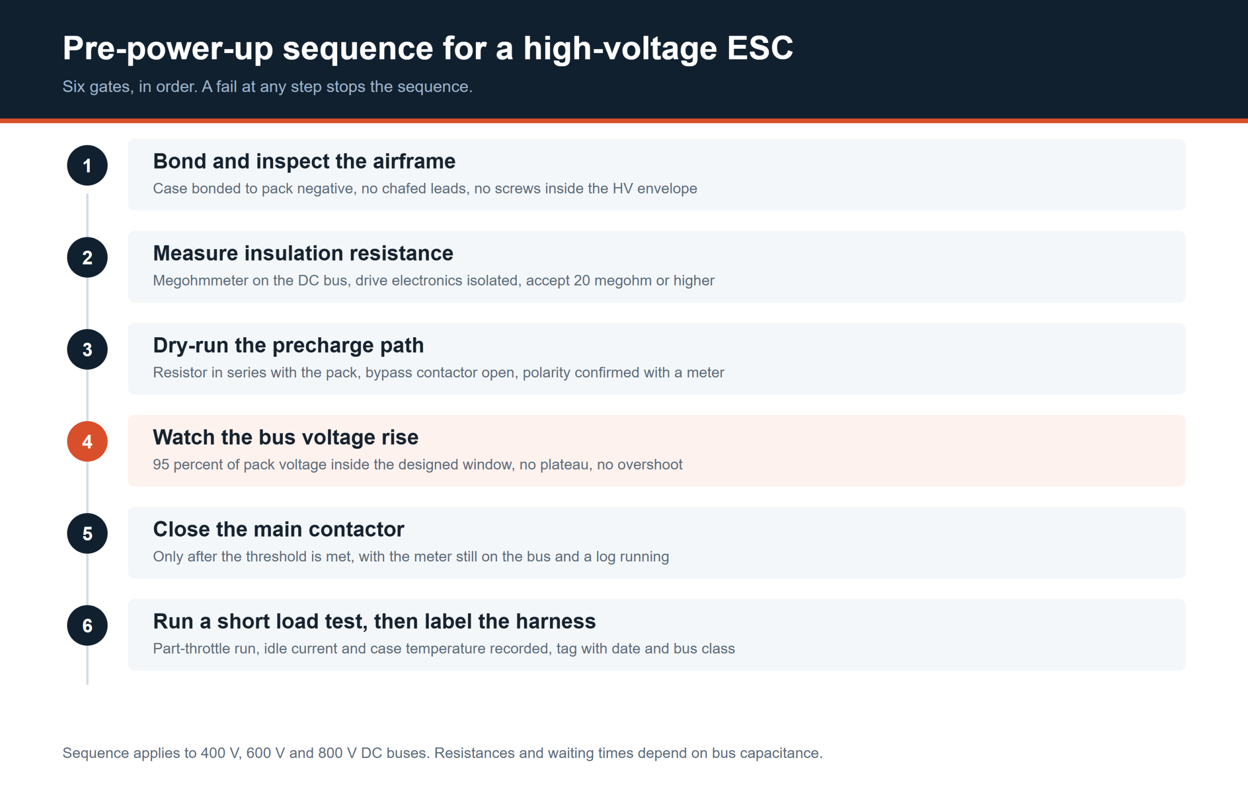 The gates in the order we run them on a new harness. Steps 2 and 4 catch the failures no amount of visual inspection finds.
How do you verify a precharge circuit before flight?
Verify it by logging the bus voltage during a real precharge and checking three numbers against the design: rise time, contactor close voltage, and resistor temperature afterwards. A circuit that passes continuity but fails any of those will still arc in service. The sequence we use, in order:
- Measure capacitance and resistance. An LCR meter across the bus gives the number the design assumed; thirty percent more than expected means the wait time is already wrong. Confirm the resistor against tolerance and write the value on the harness tag.
- Log the rise. A 100 Hz logger on the bus is enough to see the curve. Fit the time constant and compare with the measured R × C; a fit more than 15% off means the path is not what the drawing says.
- Check the close threshold. The contactor must not close before the bus reaches its threshold, and must close on the next attempt after an abort. A latched precharge that never resets is a grounded aircraft.
- Repeat three times. Three precharges with two minutes between them tells you whether the resistor has margin for a day of flying, not just one event.
- Check the bleed. With the pack removed, the bus must fall below 60 V DC within 60 s through the bleed path. An 800 V bus holding charge for ten minutes is a bench hazard.
- Then spin the motor. No-load first, restrained thrust second. The precharge is proven only once the ESC has switched current on a charged bus without a fault.
One observation from our own bench explains why the wait needs a cold corner. An 800 V bus with 2,000 µF behind 250 Ω reached 780 V in 2.6 s at 25 °C, and needed 4.1 s at −10 °C, because ESR rose and effective capacitance fell. The arithmetic said 3.4 s for 5τ at room temperature. A contactor threshold fixed at 3 s would close early in the cold, which is why the threshold should be voltage-based, not time-based. The same test doubles as a fault finder. A bus that rises faster than the fit predicts has lost capacitance, usually a dried bank; a bus that plateaus below 95% has a resistive joint in the precharge path or a leak to chassis. A 160 A class drive such as the SINESIC 160A Pro 400 V carries enough input capacitance that a hand-mated XT60 pair is not a reasonable connection method; precharge belongs on the harness drawing, not in the technician’s memory.
Procurement and documentation notes
Buying HV ESCs for a programme rather than a bench means the precharge and wiring details should arrive as documents with the hardware, because the integration risk sits in the harness. Ask for them before the purchase order.
- Samples from 1 pc. One unit is enough to measure input capacitance and confirm the precharge window on your own bus.
- Lead time. Stock configurations ship in 3–10 business days; sample orders run 7–15 business days; OEM builds run 25–40 business days, counted from sample confirmation and deposit.
- Warranty. 12 months from shipment on the ESC. The precharge resistor is a harness consumable and is quoted separately.
- Response. Engineering questions come back within 1 business day, which matters when the answer changes a harness drawing.
Cost structure, without unit prices. Drive cost is dominated by the power stage, the bus capacitor bank and the housing, and the 800 V class sits materially above 400 V at the same current because capacitor rating, creepage distance and insulation tooling all scale with bus voltage. The harness adds a smaller line: resistor, contactor, keyed connectors and the labour to crimp them. We quote ranges against a written specification, because a 30% change in bus capacitance moves the resistor class. Documentation package. Per order we can supply the wiring diagram with precharge topology, resistor datasheet with surge energy rating, terminal torque specification, insulation resistance test record, RoHS and REACH declarations, and the ISO 9001 certificate. A first-article inspection report is available on request — ask at quotation, because it changes the lead time. The full range of HV drives sits in the drone ESC category. For a harness review, send bus voltage, total capacitance and connector type and we will return a sizing note with the quotation. If a unit is already running warm on the bench, that is a different question from wiring and is covered in ESC overheating causes. Do not use a precharge resistor to mask a thermal problem.
常见问题解答
How long should I precharge a high-voltage ESC before power-up? Long enough to reach about 95% of pack voltage, roughly three time constants of the bus. With 1,000 µF and 100 Ω that is 0.3 s at 400 V; with 2,000 µF and 400 Ω it is 2.4 s at 800 V. Measure the rise rather than assuming it. Can a resistor-equipped anti-spark connector replace a precharge circuit? Only below roughly 500 µF of bus capacitance. The resistor inside an anti-spark connector is a 1–2 W part sized for a small bank, and it overheats on a 2,000 µF 800 V bus. Above that, use an external resistor and a contactor. What wire gauge do I need for an 800 V ESC? Gauge follows current, not voltage: 6–8 AWG silicone cable for a 160 A continuous drive, with insulation rated above the bus. Voltage drives insulation and spacing, current drives copper. Keep DC drop under 3% at rated current and support the cable every 150 mm. What insulation resistance should a high-voltage ESC pass? 20 MΩ or higher from the DC bus to chassis, measured with a megohmmeter and the drive electronics isolated. Low megohms indicates moisture, contamination or a damaged harness. Record the value, test voltage and ambient conditions on the build sheet so the next test has a baseline. Why does my precharge resistor get hot or fail open? Because it absorbs ½CV² on every power-up, and energy rather than resistance value is what destroys it. An 800 V, 2,000 µF bus delivers 640 J per event. A part without a stated surge rating drifts in value or opens, and an open resistor silently removes the protection. Do I need precharge on a 400 V pack? Yes. 400 V is well above the point where a DC arc sustains across a parting contact, and a 1,000 µF bank holds 80 J at that voltage. The resistor is smaller and the wait shorter than at 800 V, but the sequence and the damage without it are the same. All products are supplied for civil end use only.
About the author. REACHSKY Engineering Team — power stage, thermal and harness integration for UAV propulsion. Last updated 2026-11-09.
相关文章
-
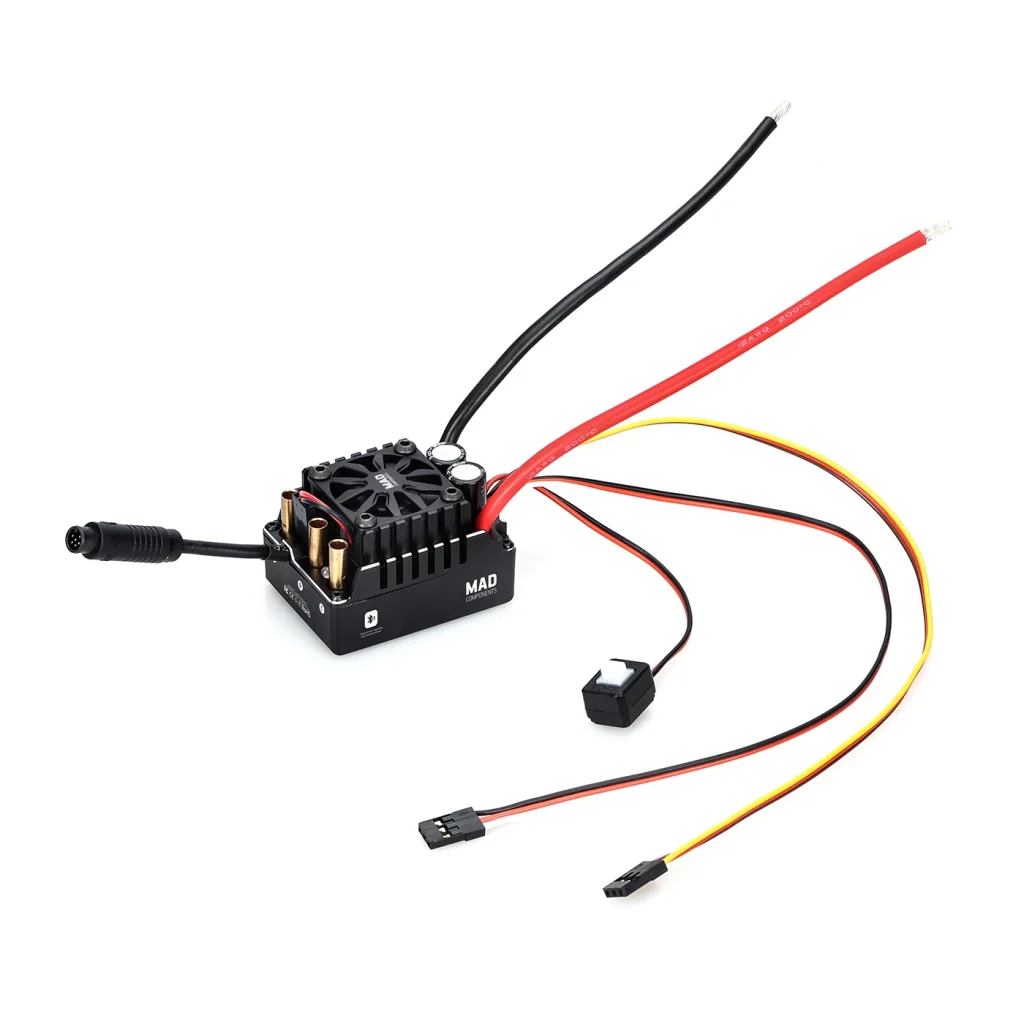 RC Car ESC Selection: MAX Series for 1/5 to 1/10 Scale
Two 1/5-scale vehicles can ask very different things of an ESC. Battery configuration, motor, gearing, tires and driving conditions all affect the job. A scale label narrows the…
-
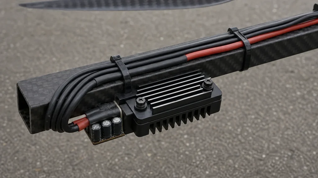 ESC Overheating Causes and How to Fix Them
Six causes of ESC overheating, ranked by how often they are the real problem, plus the order to measure them in and how to prove the fix held.
-
 DShot, OneShot and PWM: ESC Protocols Explained
A flight controller and an ESC can share the right battery voltage and still fail to communicate. The throttle command needs its own compatibility check: the controller must…
-
 SineSic FOC ESC Voltage Classes: 400V, 600V and 800V Compared
Primary keyword: sinesic foc esc voltage classes TL;DR A SineSic voltage class fixes the DC bus window and the insulation target. It does not fix the output power,…