


ESC Overheating Causes and How to Fix Them
Six causes of ESC overheating, ranked by how often they are the real problem, plus the order to measure them in and how to prove the fix held.
TL;DR
- Most ESC overheating causes are downstream of the ESC: a continuous rating chosen for burst duty, a propeller that moved the operating point, blocked fins, a sealed compartment, or a resistive DC path. The controller is usually the last thing that is actually wrong.
- Temperature must be measured at load, at the heat sink base, for the length of a real mission. A single full-throttle burst on the bench tells you almost nothing about a 12-minute climb profile.
- Work the chain in one order — temperature, rating, prop load, drive settings, installation, DC path — and stop at the first cause the logged data supports. Each step is cheaper than the next, and none of them is a new ESC.
An ESC that runs hot is not automatically an ESC that is failing. It is a controller reporting, through temperature, that the energy it is asked to switch does not match the path it has for getting rid of the loss. This guide separates the six ESC overheating causes we see most in warranty returns and field logs, gives the order to check them and the number that counts as abnormal.
Heat is a symptom, not a fault code
An ESC converts DC into three-phase AC by switching six or twelve power devices on and off thousands of times per second, and every switch event costs energy. Those losses land in two places: conduction loss, which scales with current squared and the on-resistance of the FETs, and switching loss, which scales with bus voltage, PWM frequency and how cleanly the gate drive turns the device off.
The practical consequence is that heat rises faster than load. Doubling the current through a resistive channel roughly quadruples the conduction loss, so a setup running at 60% of its rated current is not at 60% of its thermal stress.
Cause 1: The continuous current rating is smaller than the real duty cycle
This is the most common ESC overheating cause in commercial airframes, and the least visible, because the aircraft still flies. A drive rated at 80 A continuous is bought for a motor that pulls 55 A at hover, which looks like a comfortable margin. Then the mission adds a 15% payload, a headwind leg and a climb, and average current sits near 70 A while peaks touch 100 A.
Two things break the margin at once. Conduction loss grows with the square of current, so 70 A against an 80 A rating is not 88% of the thermal load — it is close to the full design load, with no headroom left for a hot day. And the rating was probably measured on an open bench, not inside a fuselage with the ESC wrapped in a cable bundle.
The fix is arithmetic, not intuition. Take the logged current for a full mission, sort it by time, and look at the sustained band rather than the peaks. If more than a third of the flight sits above 70% of the continuous rating, the class is undersized for that mission even if nothing has failed yet. Move up one rating step, or reduce the load, and log again. Our own continuous versus burst current rating note covers how those two numbers are defined.
Cause 2: The propeller load moved past the design point
An ESC does not decide how much current flows. The propeller does. Change diameter, pitch, blade count or blade material and the operating point moves, often further than the label suggests. A 1-inch increase in diameter at constant pitch can add well over 20% to the power required at the same RPM, and the ESC sees all of it as current.
The failure pattern is easy to recognise: fine at hover, hot at the top of a climb, hot during a braking descent. Hover current is a poor proxy because hover is the cheapest point in most missions; what matters is current at the highest sustained thrust, held as long as the mission holds it.
- Diameter raises torque demand quickly and is the first thing to question after a prop swap.
- Pitch raises the current at a given RPM and pushes the motor down its curve.
- Blade count adds solidity; three blades at the same diameter and pitch draw more than two.
Cause 3: Timing, firmware and commutation are fighting the motor
Timing advance that suits one motor can overheat another. Too little and the current lags the back-EMF, so the controller pushes more current for the same torque. Too much and phase current peaks early, which lands as heat in the FETs. Neither condition throws a fault; both look like a cooling problem.
The settings that matter, in the order we check them:
- Timing advance: start low, raise only if the motor stutters at low throttle or loses sync under acceleration. High advance buys top-end RPM and costs heat everywhere else.
- PWM frequency: higher frequency smooths current but raises switching loss. Low-inductance motors often need it; large ones usually do not.
- Demag compensation: protects against desync during fast throttle changes. Too aggressive and it limits power; too low and a desync dumps current into one phase pair.
- Startup power and ramp: a hard start into a large prop is a current spike the FETs absorb as heat.
- Firmware target: a build compiled for a different board revision or a different gate driver can run, arm and fly while switching at the wrong dead time.
The reference documentation for open firmware platforms, such as the Betaflight documentation and the BLHeli_32 firmware site, lists which parameters are safe to move and which reset on a firmware flash. When a unit comes back hot with no visible damage, comparing its saved settings against the defaults for its class is faster than any bench test.
Cause 4: The heat sink has no path to moving air
A heat sink without airflow is a heat spreader with no buyer for its surface area. Most installs put the ESC where the wiring is shortest — under the flight controller stack, inside the arm tube, against the frame plate — usually the worst place thermally.
Fin geometry only works when air can enter at the base of the fins and leave at the tip. Three common installs defeat it:
- Fins parallel to the airflow, so air passes across the fin edges instead of through the channels.
- Fins against a plate or a battery, which closes the channel and turns the heat sink into an insulator.
- Cables routed across the fin field, which is common on builds where the ESC sits between the pack and the motors.
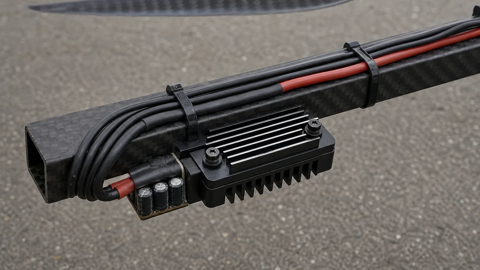
Heat leaves an ESC through the heat sink base and the fin surfaces; the FETs and the PCB underneath reach their limits long before the outside of the case feels hot.
Check the install in this order: heat sink base in contact with the case, case in moving air, fin channel open at both ends, nothing behind the ESC hotter than the ESC. 10 mm clearance at the fin tips is a working minimum on most 12S to 14S builds; 20 mm is better.
Cause 5: Ambient temperature and sealed avionics bays
Ambient temperature does not add heat; it removes the gradient heat needs to leave. An ESC rated for 80 A at 25 °C has a smaller envelope at 45 °C, and the derating is not linear.
Sealed bays make it worse in a way that is easy to miss. A closed compartment with no inlet and no outlet reaches thermal equilibrium with its own losses, so the air around the ESC climbs until the case-to-air difference shrinks and the ESC’s ability to shed heat collapses. In flat-top agricultural and inspection airframes, we have seen bay air run 15 to 20 °C above outside air after a few minutes of hover, which is the equivalent of moving the whole mission to a hotter day.
Countermeasures, in order of cost:
- Open a path: two vents at opposite ends of the bay, one low and one high, so convection can work when the props are stopped.
- Derate for the site: for operations above 35 °C ambient, treat the continuous rating as roughly 80% of the datasheet figure and check the log against that.
Cause 6: Harness and connector contact resistance
Every milliohm between the pack and the ESC becomes heat, in the worst possible place: the connector body and the first 30 mm of wire, where there is no heat sink at all. A resoldered connector, a bullet that has lost its spring or a wire gauge chosen for the old 60 A setup all raise loop resistance and lower the voltage the ESC actually sees.
The ESC compensates for that sag by raising duty cycle to hold RPM, which raises current through the same resistive path. The result is a controller that runs hot while the connectors and wires are also warm — a pattern that points at the DC side.
Four items decide it:
- Wire gauge against sustained current, not peak. Undersized leads are common on rebuilds.
- Connector condition: discoloured housings, blackened pins, any sign of arcing on the mating face.
- Solder joints: a cold joint reads as resistance and heats under load.
- Bulk capacitors: a dried or bulged capacitor raises ripple, and ripple current adds loss inside the controller.
Measure the DC path with a milliohm meter, four-wire, from pack terminals to ESC pads, harness in place, and compare against the sum of connector and wire specification; a joint reading several milliohms high is a joint to redo.
Which ESC overheating causes should you check first?
Start with temperature at load, then the rating, then the load itself, then drive settings, then the install, then the DC path. The order runs from the cheapest measurement to the most expensive intervention, and it stops at the first cause the logged data supports.
Step 1 — Log temperature at load. Bond a thermocouple to the heat sink base, fly five minutes at hover-equivalent throttle, then repeat the mission climb. Record case temperature, ambient, current and throttle together; a temperature without current beside it cannot be read.
Step 2 — Compare against the rating as written. Match logged current to the continuous figure, then check the ambient, mounting and cooling the datasheet assumed. At 45 °C in a sealed bay, compare against a derated figure.
Step 3 — Check the prop load. Compare current at hover thrust and at maximum continuous thrust against the motor’s thrust table. Diameter, pitch and blade count each move the operating point, and a prop change is the most common trigger.
Step 4 — Check drive settings. Timing advance, PWM frequency, demag compensation, startup power and the firmware target for that board, checked against class defaults before anyone’s tune.
Step 5 — Check the installation. Heat sink contact, fin clearance, cables crossing the fin field, and whether air can enter and leave the compartment. Photograph the routing first.
Step 6 — Check the DC path. Wire gauge, connector condition, solder joints, bulk capacitors, and loop resistance from pack terminals to ESC pads against the calculated harness value.
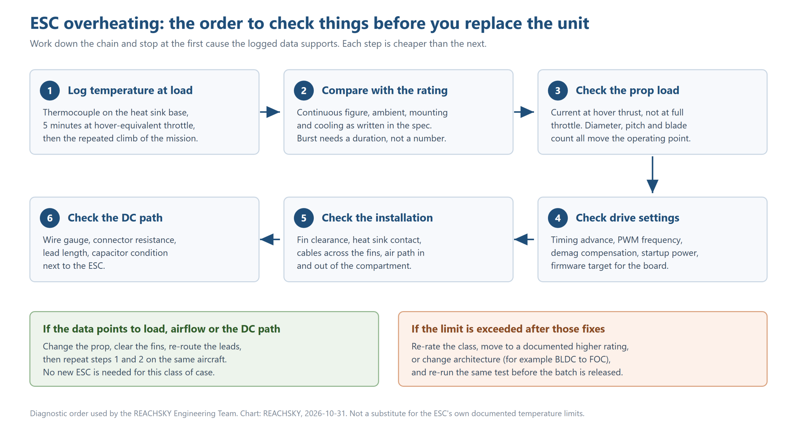
The order used by the REACHSKY Engineering Team: each step is cheaper than the one after it, and the branch after step 6 decides whether the fix is mechanical or a re-rating.
What reading points to which cause?
Fixes that hold, and how to prove them
A fix is only a fix if the same aircraft repeats the same mission cooler. Change one variable at a time, then re-run steps 1 and 2 in the same log format.
- Load side: drop an inch of diameter, reduce pitch, or fit a lighter blade. Re-check hover thrust before accepting the loss.
- Thermal side: align fin channels with the airflow, open the bay, add fin-tip clearance, or move the unit into prop wash.
- DC side: replace tired connectors, shorten leads, increase gauge.
- Rating side: one step up in the same family — the AMPX 200A (12-24S) HV class, for example — or a change of architecture, as our BLDC versus FOC ESC comparison sets out.
Verification means three flights, not one: accept the fix only if case temperature plateaus below the derated limit on all three, with no protection event in telemetry.
The B2B view: batch returns, warranty calls and repeat lots
ESC overheating is a purchasing problem before it is an engineering one. When an operator reports five hot units from one lot, the commercial outcome depends on whether the cause sits in the product or in the application, and that question is answered by data collected before the return, not after it.
Three practices cut the cost of the cycle. Log before you return — a claim without a flight log, ambient temperature, prop specification and drive settings cannot be adjudicated, so those four items travel with every claim. Start at the quality channel with the PO number and lot code. Separate the failure classes — a desoldered FET, a bulged capacitor and a derated-but-alive unit are three different outcomes, and mixing them in one spreadsheet hides the trend that would have prevented the next lot. Fix the specification, not just the unit — if a batch shipped against a 70 A hover current and returned hot because the mission runs at 95 A, replacing drives changes nothing. Re-rate the class, update the BOM, and write the derating rule into the technical file.
For OEM and private-label programmes the same logic applies earlier: test samples at the customer’s maximum continuous thrust, ambient and bay geometry, not on an open bench at 25 °C. Standard warranty is 12 months unless the quotation states otherwise; OEM builds run 25–40 business days from artwork approval and deposit.
Frequently Asked Questions
How hot is too hot for a drone ESC? Case temperature above roughly 70 °C at the heat sink base, at the ambient the aircraft actually flies in. Most controllers derate before the junction limit, so a unit that throttles back in a climb is already outside its thermal design.
Why does my ESC overheat only after a prop change? The propeller sets the current. More diameter, more pitch or an extra blade raises it at the same RPM, so the ESC holds a higher duty cycle. Compare hover and maximum continuous current against the motor thrust table first.
Can firmware cause ESC overheating? Yes. Timing advance, PWM frequency, demag compensation and startup power change how much current the controller pushes for a given torque, and a tune from a small high-KV motor runs hot on a large low-KV one. Retune one parameter at a time.
Does a bigger ESC always run cooler? Not by itself. A larger drive has more silicon and heat sink area but different switching behaviour. One step up helps when the log shows sustained current at the old limit; it does nothing when the cause is blocked fins or a bad connector.
How do I know the fix worked? Repeat the mission three times and compare case temperature, sustained current and protection events against the original log. A plateau below the derated limit on all three flights, with no throttle cutback, is the acceptance criterion. One cool-weather flight proves nothing.
About the author — REACHSKY Engineering Team, Changsha, Hunan. We specify, test and support propulsion hardware for commercial UAV programmes, including thermal validation on our own benches. Airframe questions go to /contact/?intent=oem; the drone ESC range lists current ratings and voltage classes.
All products are supplied for civil end use only.
Last updated: 2026-10-31
Artículos relacionados
-
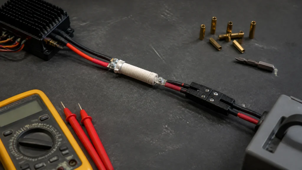 High Voltage ESC Wiring Precharge: Steps Before Power-Up
Why an 800 V connector arcs on contact, how to size the precharge resistor, and the six-gate checklist we run before an HV ESC sees pack voltage.
-
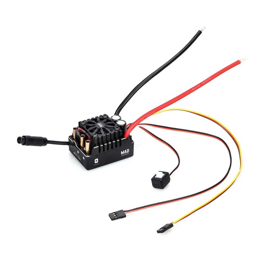 RC Car ESC Selection: MAX Series for 1/5 to 1/10 Scale
Two 1/5-scale vehicles can ask very different things of an ESC. Battery configuration, motor, gearing, tires and driving conditions all affect the job. A scale label narrows the…
-
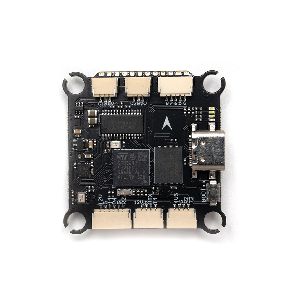 DShot, OneShot and PWM: ESC Protocols Explained
A flight controller and an ESC can share the right battery voltage and still fail to communicate. The throttle command needs its own compatibility check: the controller must…
-
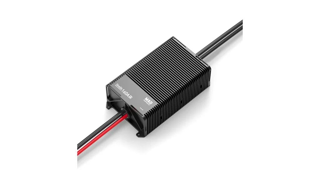 SineSic FOC ESC Voltage Classes: 400V, 600V and 800V Compared
Primary keyword: sinesic foc esc voltage classes TL;DR A SineSic voltage class fixes the DC bus window and the insulation target. It does not fix the output power,…