


重型无人机电机内部结构:磁铁、通风口和轴
TL;DR
- Segmented arc magnets reduce eddy-current loss inside the rotor. That is why heavy-lift and VTOL motors stack many small magnet blocks instead of one large arc.
- The honeycomb mesh over the rotor openings is a filtered intake. It keeps sand, gravel and crop debris out of the air gap while still letting the rotor breathe.
- A threaded shaft deletes the prop adapter and the separate prop nut. Fewer parts to loosen — but the thread now carries the full thrust preload.
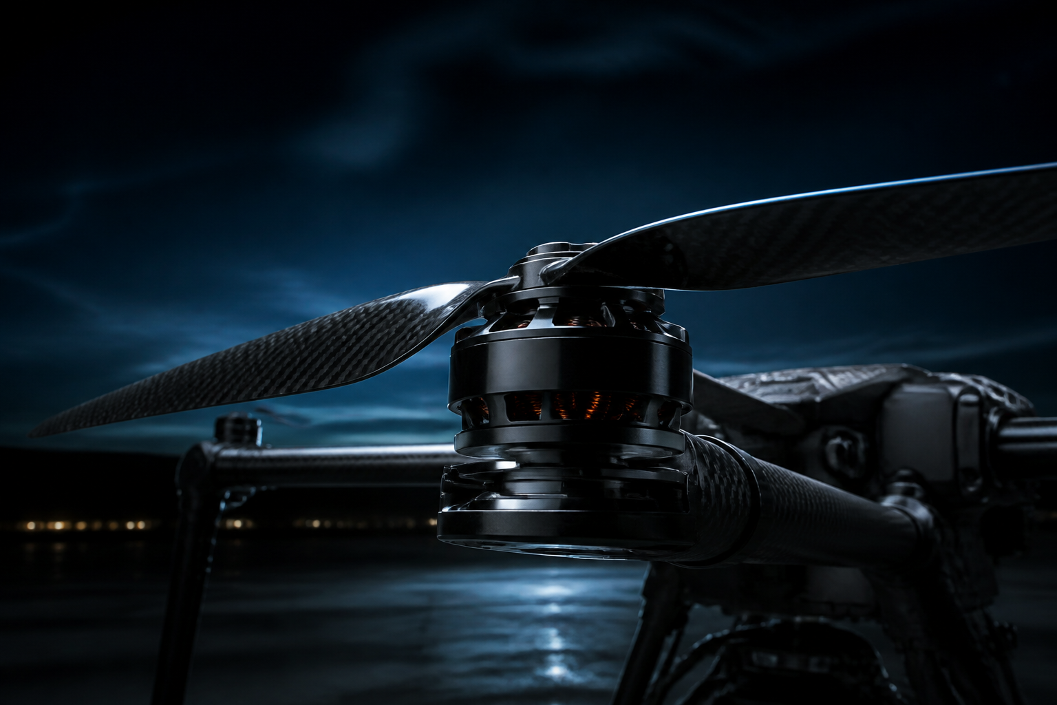
Two photos of the same heavy-lift drone motor, shot from the outside and from inside the rotor bell. Between them they show three decisions that shape efficiency, cooling and field reliability: how the magnets are made, how the rotor is vented, and how the propeller attaches.
Here is what each decision does, and where each one bites.
What the two photos show
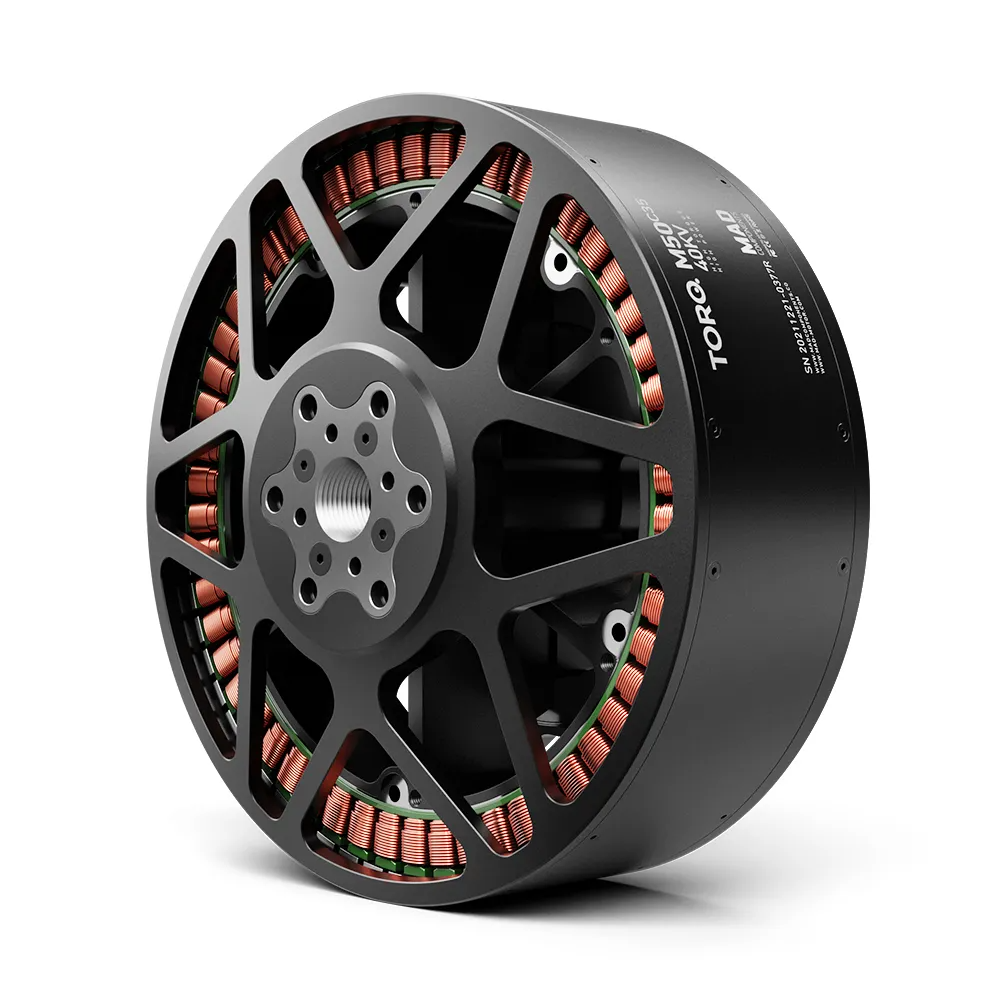
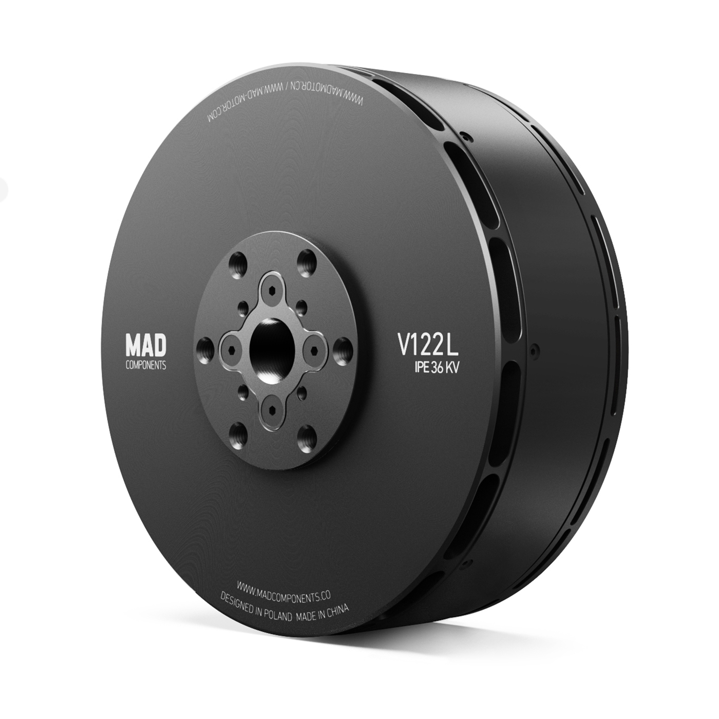
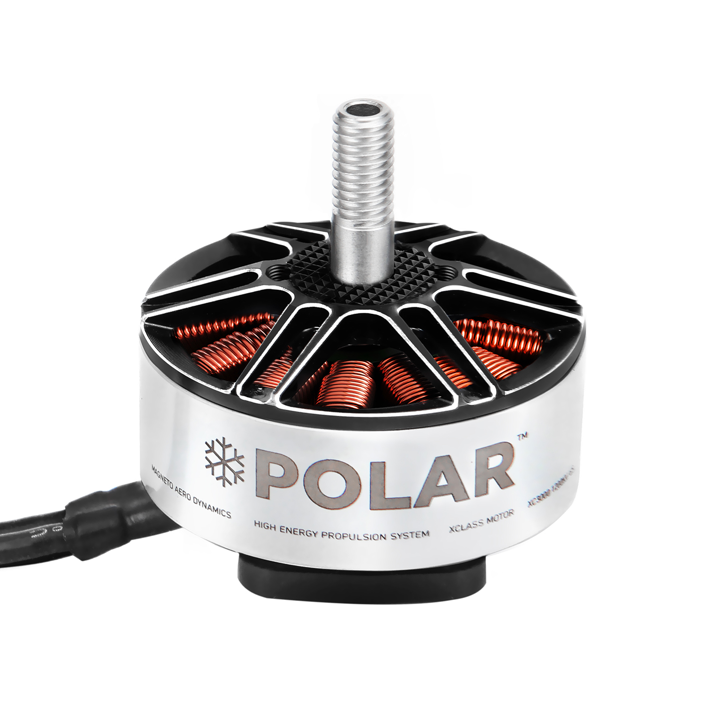
The assembled motor: a black anodised aluminium can, machined cooling ribs at both ends, a six-spoke rotor top closed by honeycomb mesh, and a long threaded steel shaft with no prop adapter fitted. Held in a hand for scale, the can is roughly palm-width across.
The opened rotor bell shows the other half of the story. Set into the inside wall is a ring of separate magnet blocks, each a short arc with a visible gap to its neighbour. In the centre, a six-spoke spider in red anodising carries the bearing and its retaining ring. The same honeycomb mesh sits behind the spokes.
Two production details matter as much as the engineering. The bell is packed in EPE foam inside a carton carrying a barcode, and further rotors sit in bags behind it. This is a motor being built in lots, not a hand-made sample.
Why heavy-lift motors use segmented magnets
The eddy-current problem
A permanent-magnet rotor spins inside a magnetic field that contains harmonics: slot harmonics from the stator, plus the ripple in the current waveform your ESC delivers. Those harmonics induce circulating currents inside the magnets themselves.
The magnets are conductive. The currents run, and the losses land as heat in the one place you cannot cool — inside the rotor, behind the air gap, at the far end of a thermal path that runs back through the shaft and the bearings.
The higher the electrical frequency, the worse it gets, and both pole count and RPM raise it. That is why heavy-lift and VTOL motors — many poles, long duty cycles, high continuous load — are the class where magnet loss stops being a rounding error.
What segmenting actually does
Cut the arc into blocks and you cut the path the circulating current can take. Each block is electrically small, so the current induced in each one is small. Published work on rotor loss in surface-mounted permanent-magnet machines lists axial and radial segmentation of the magnets as one of the standard routes to reducing it, alongside slotless topologies and grooving the retaining sleeve — see this open-access paper from the University of Huddersfield.
Three effects follow, and only the first is obvious:
- Lower rotor loss. Less heat generated inside the rotor means less heat to remove from it.
- Better behaviour at high electrical frequency. The benefit scales with frequency, so it appears exactly in the operating region a heavy-lift motor lives in.
- Easier manufacturing. One large sintered arc is harder to press without cracking, and more exposed to thermal-shock cracking, than a set of small blocks. Segmentation spreads that risk across parts.
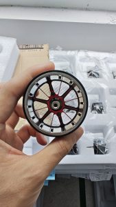
The trade-off you pay for
Blocks have edges. Every gap between them is a discontinuity in the magnetic circuit — a place where flux leaks and the field becomes slightly less uniform. The consistency of that gap, including the bond line and glue thickness, stops being a design constant and becomes a manufacturing tolerance.
Two consequences belong in your acceptance criteria:
- Cogging torque is a design task, not a side effect of segmentation. Segmenting the magnets does not remove cogging on its own. The span and relative position of the blocks change it, so the outcome depends on how the segmentation is designed. Reducing it further usually takes deliberate rotor or stator work — this study on segmented-magnet BLDC motors used stator skew and reports an almost complete cogging reduction in its simulations. Do not assume a segmented rotor is a smooth rotor.
- Cogging torque is a low-speed problem. It is inherent to any permanent-magnet machine, because the stator and rotor always interact magnetically. It shows up most at moderate load and low speed, where inertia can no longer smooth the output, and you experience it as noise and vibration.
What the honeycomb mesh is for
The rotor openings exist to let air move. Left open, they are also a direct path for anything the propeller throws: sand, gravel, crop debris, chaff.
The mesh turns those openings from an open slot into a filtered intake. Debris that would otherwise reach the air gap and score the stator or jam the rotor meets the screen instead, where it can be cleared.
The cost is airflow. A mesh reduces the open area of the vent, so less air moves through it at the same rotor speed. You are deliberately trading peak cooling for protection against foreign-object damage.
Which way to go is a mission question, not a spec-sheet question. A motor flown from a paved surface or a clean field gains little from a screen. A motor on an agricultural platform or a dusty site gains a great deal. This is one of the things worth raising when you specify a platform, rather than ordering by KV alone.
Maintenance is not optional. A screen that is never cleared clogs, and a clogged screen is worse than no screen: you have paid the airflow penalty and lost the cooling benefit with it. Add screen inspection to your pre-flight or scheduled maintenance interval, whichever comes first in your operation.
Threaded shaft instead of a prop adapter
The motor in the photo has a bare threaded shaft — no prop adapter, no separate prop nut.
What you gain: fewer parts in the stack, one less threaded joint that can back out, and faster assembly. On a fleet maintained by technicians rather than enthusiasts, removing a joint is worth more than it looks. The failure you never have is the cheapest one.
What you take on:
- Thread direction has to match the rotation. A thread that tightens under thrust is self-tightening; get the direction wrong and the prop works the nut loose. If you run the same motor in tractor and pusher configurations, verify per build rather than per model.
- Side loads land on the shaft. The shaft is long and unsupported past the bearing. A ground tip-over or a prop strike bends it, and a bent shaft shows up as vibration long before it shows up as a visible bend. Check runout; do not rely on the eye.
- The thread carries the full preload. With an adapter, clamping force spreads across a flange. Here it concentrates in the thread and the shaft shoulder. Torque it to the manufacturer’s value rather than to feel.
The machined ribs
Both ends of the can carry machined ribs. They add surface area, and because the can turns, they also help move air across it. Nothing exotic — it is the cheapest cooling you can put on a motor, and its absence is a signal that the motor was dimensioned for short bursts rather than continuous duty.
Read the ribs together with the vents: the ribs cool the outside of the can, the vents let air reach the inside. A motor with one and not the other is doing half the job.
How to evaluate a heavy-lift drone motor before you commit
Start from the datasheet. These photos cannot tell you the model, stator size, KV, recommended cell count, propeller, continuous current or weight — and no one should compare heavy-lift motors without those numbers. Ours are listed against the motor families we supply.
Then check the things datasheets usually leave out:
Common mistakes with heavy-lift motors
If any of that lands on an open question, the FAQ section covers the recurring ones on arm sets, motors and FOC matching.
Frequently Asked Questions
Why do heavy-lift motors use segmented magnets instead of one-piece arc magnets?
Segmentation cuts the path circulating eddy currents can take inside the magnets, so rotor loss and rotor heat drop, especially at high electrical frequency. It is also easier to manufacture several small blocks than one large arc without cracking. The gaps between blocks are the price, because they have to be held to a tight and consistent bond line.
Do the mesh vents on a drone motor reduce cooling?
Yes. A mesh reduces the open area of the vent, so less air moves through it at the same rotor speed. The trade is deliberate: you accept lower peak cooling in exchange for keeping sand, gravel and crop debris out of the air gap, where they would score the stator or jam the rotor.
Is a threaded shaft better than a prop adapter?
It depends on who maintains the aircraft. A threaded shaft removes a joint and speeds assembly, which is a genuine gain in fleet service. In exchange, the thread must match the rotation direction, the shaft absorbs side loads directly, and the thread carries the full thrust preload.
What causes cogging torque, and does segmentation remove it?
Cogging torque comes from the magnetic interaction between the stator and the rotor, and it exists in every permanent-magnet machine. It is most noticeable at low speed and moderate load, where it appears as vibration and noise. Segmentation changes cogging torque and can reduce it, but only when the block span and block positions are chosen for that purpose.
How often should I clean the mesh screens?
Tie it to the environment rather than the calendar. On a dusty or agricultural site, inspect before every flight day. Long-endurance missions in clean air need far less. The rule is simple: a clogged screen is worse than no screen, because you still pay the airflow penalty without gaining the protection.
How do I choose a heavy-lift drone motor for my payload, voltage and propeller?
Work from the operating point, not the part number. Start with total takeoff weight, divide it across the number of motors to get thrust per motor, then shortlist the motors that reach it at a hover throttle you are willing to accept. Fix the cell count and propeller next, and only then compare motors.
What does a bent shaft actually cost me?
More than the shaft. A bent shaft appears as vibration that grows with RPM, then as bearing wear, then as inconsistent thrust. Check runout on the unsupported portion rather than looking for a visible bend, and treat every prop strike as a runout check.
Matching the motor to the platform
Before you lock a heavy-lift motor SKU, get three decisions right: how the magnets are made, how the rotor is vented, and how the propeller attaches. Everything else — KV, thrust tables, current ratings — only means something once those three match your mission. Start from the motor range and the propeller range, then work outward to the ESC that has to drive it.
If you are matching a platform and want a second pair of eyes on the numbers, send your payload, target thrust, voltage, quantity and destination market. Our application engineers return a matched setup, MOQ, compliance documents and lead time — not a generic catalog reply.
Prefer to run the numbers yourself first? The motor datasheets, CAD files and propulsion matching checklist are available to download. If you want technical background on rotor loss and magnet segmentation, the papers linked above are open access.
This article was written by the REACHSKY Applications Engineering Team. We supply brushless motors, ESCs, propellers, batteries and integrated power systems to UAV integrators, distributors and OEM programs in North America, South America and Europe. All products are supplied for civil end use only.
Once you shortlist a heavy-lift drone motor, pair KV and battery voltage carefully — start with motor KV and battery voltage matching.
相关文章
-
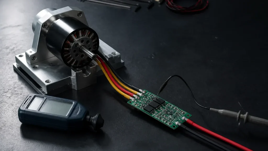 Motor Desync High Current: Causes and Fixes
Why a motor loses commutation exactly when current climbs, the six causes in the order worth checking, and a bench routine that makes desync repeatable.
-
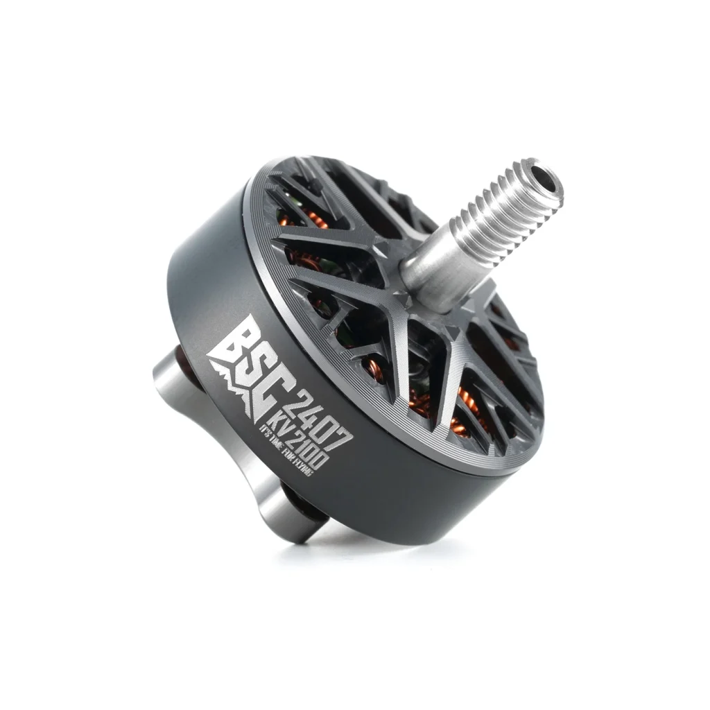 FPV Motor Series Explained: BSC, CM, FS and KONKER
A series name helps you find a motor. It does not finish the selection. ??inematic??is not a payload rating, ??reestyle??is not a battery specification, and ??asic??does not tell…
-
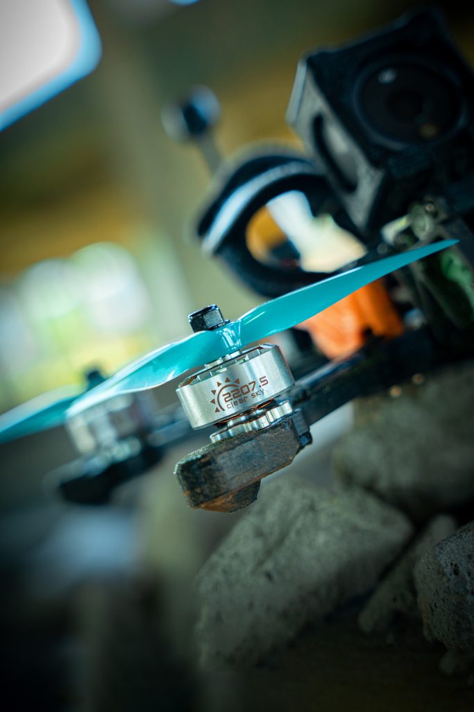 Drone Motor Bearing Maintenance and Replacement Intervals
A motor that sounds different after a prop strike needs an inspection, even if it is far from its planned service date. A motor that sounds unchanged still…
-
 Heavy-Lift Drone Motor Selection: Payload, Thrust and Redundancy
A step-by-step heavy-lift drone motor selection method: payload to all-up weight, thrust per arm, redundancy reserve, then a datasheet check on the AM110.