


Coaxial vs Single Drone Arm Sets: When to Use Which
Coaxial vs Single Drone Arm Sets: Comparison Guide
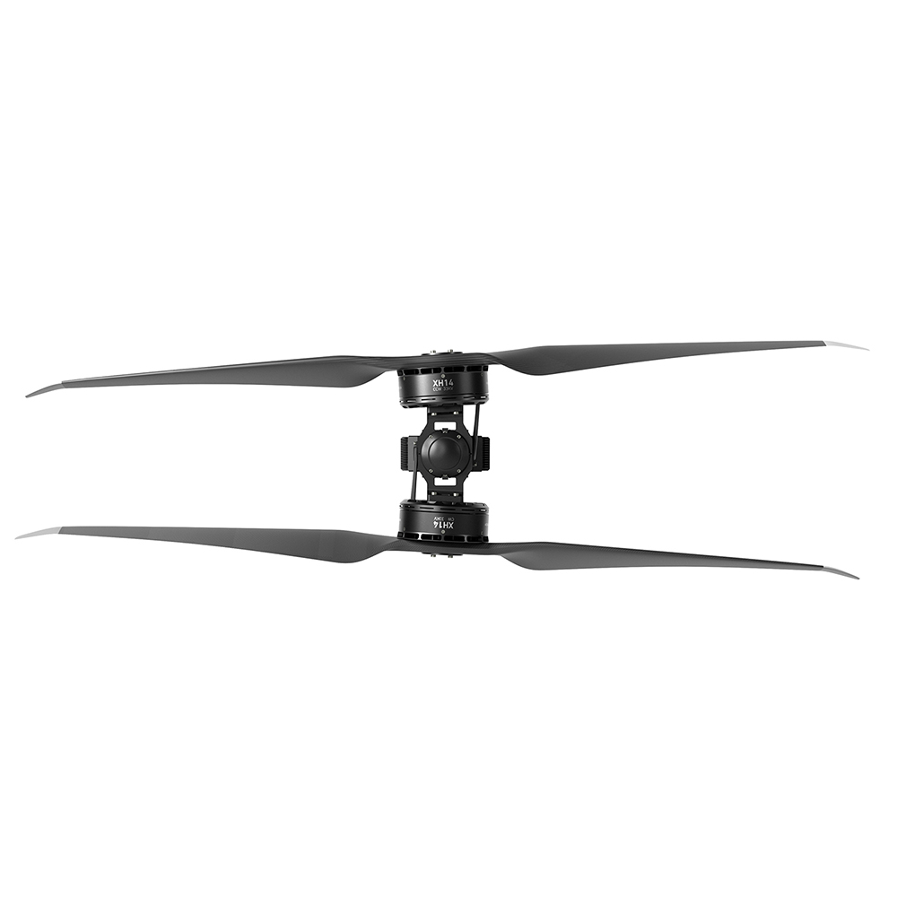
When the airframe cannot grow wider, adding another propulsion unit is not simply a matter of extending an arm. A coaxial drone arm set places two rotors on a common axis, using vertical separation to fit another rotor into substantially the same projected location.
That can help a packaging problem. It also creates an aerodynamic interaction, another propulsion unit to service and a different installation to validate. Two motors on one arm do not automatically deliver twice the useful thrust or guarantee a safe landing after a failure.
Choose between coaxial and single-rotor arms from the available rotor space, the required installed performance and the service plan. The comparison needs a defined aircraft constraint.
What changes when two rotors share an axis?
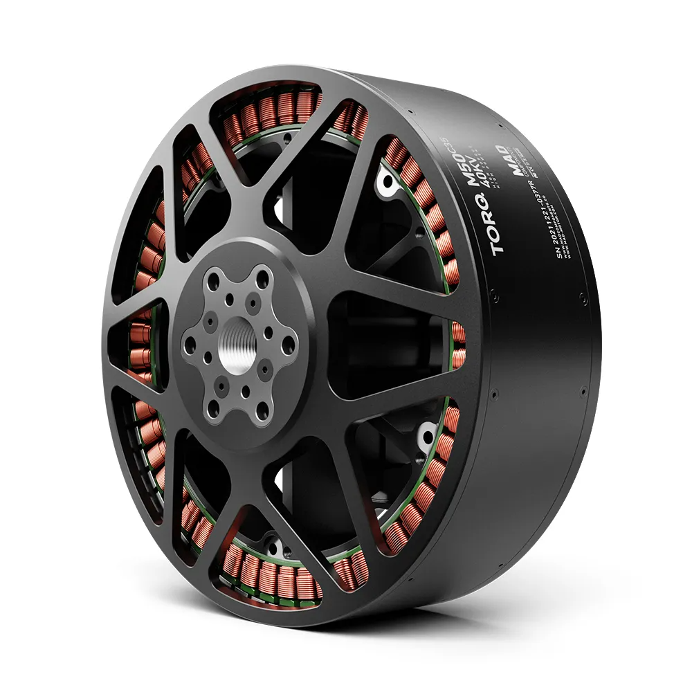
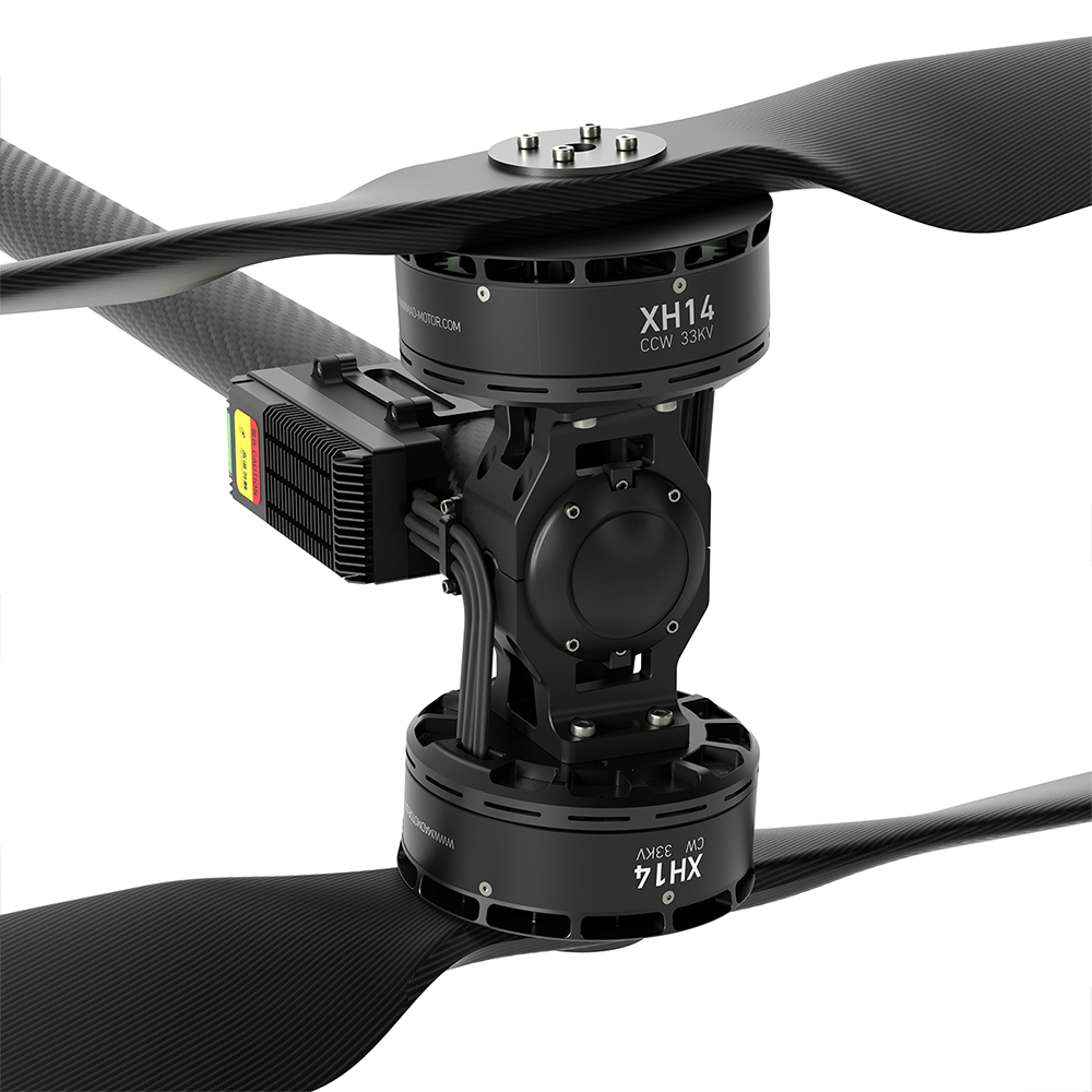
A single-rotor arm carries one motor–propeller unit. A coaxial arrangement places an upper and lower rotor on the same axis. The XH14 listing offers counter-rotating top/bottom combinations, but the correct option still depends on the airframe’s rotation map.
该 coaxial power-system category contains complete configurations to investigate. Verify the chosen set’s drawing and packing list; a category name does not establish its tube, harness or mounting interfaces.
The packaging advantage is a projection, not free disc area
Consider two equal-diameter rotor discs. If they sit separately without overlap, their combined projected area is twice the area of one disc. Stack them on the same axis and their plan-view projections overlap.
This is a geometric comparison, not a thrust calculation. For a rotor diameter D, one circular disc has area πD²/4. A coaxial pair does not create twice that projected footprint just because it has two rotors.
The arrangement can therefore place more propulsion hardware within a constrained horizontal layout. It still needs vertical clearance, arm attachment space and access to the lower rotor. The complete aircraft also has to clear adjacent blades, landing gear, payloads and obstacles.
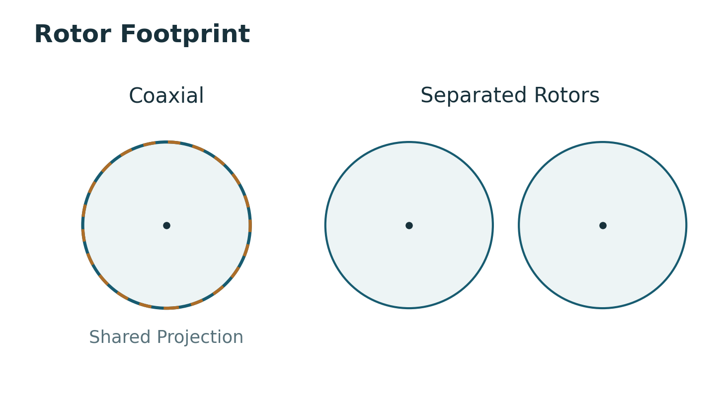
Before comparing designs, state what remains fixed: rotor diameter, aircraft width, total mass, input power or required thrust. An answer under one constraint may not apply under another. A footprint-limited aircraft and an endurance-led aircraft can reasonably choose different layouts.
Use data from the coaxial assembly
The lower rotor operates in flow influenced by the upper rotor. Rotor spacing, operating speed and load sharing affect the result. NASA’s survey of coaxial rotor aerodynamic research identifies separation distance, load sharing and wake structure as important issues. It concerns helicopter rotors and supports the general caution; it is not an XH14 qualification report.
For a purchase decision, ask for the actual coaxial configuration’s thrust and electrical-input data. Adding two isolated-motor table rows does not establish the assembled pair’s performance. Avoid applying a fixed interference percentage from an unrelated study.
Compare candidates at the aircraft’s required thrust, then check the higher-load duty separately. Record whether electrical input covers both controllers and whether the report measures total pair thrust or individual rotor thrust. Those boundaries must match before a thrust-per-watt comparison means anything.
The XH14 page includes a manufacturer performance graphic labeled for MAD XH14 33KV, FLUXER PRO 55×22-inch propellers and FOC 150A (24–28S). Its printed conditions identify 96 V, 25°C and sea level. That is published product material, not a new REACHSKY test performed for this article.
The available graphic does not supply the underlying numeric rows or a complete sustained-duty record. This article therefore does not extract precise current points from the curve or claim an efficiency advantage over a single-rotor arm. Request the source report before using those values to approve an airframe.
What the XH14 listing actually lets you specify
该 XH14 同轴无人机机臂套装 offers a 33KV selection and two top/bottom rotation options. Its manufacturer graphic identifies a propulsion combination, which is more useful than choosing a controller and propeller from appearance alone.
| Item | Published information | Remaining check |
|---|---|---|
| Motor selection | XH14, 33KV | Confirm the current hardware and drawing revision. |
| Rotation options | CW top + CCW bottom; or CCW top + CW bottom | Confirm viewing convention, blade orientation and aircraft position. |
| Graphic’s propeller combination | FLUXER PRO 55×22 in | Obtain the exact blade and hub identification. |
| Graphic’s ESC combination | FOC 150A, 24–28S | Confirm current definitions, pack limits and controller configuration. |
| Graphic’s total system mass | 8,730 g ±2%, including propellers | Confirm the supplied configuration and what the quoted mass includes. |
These are published product specifications and configuration labels. They are not a complete compatibility approval for your frame. In particular, a 33KV option does not establish every allowable voltage or propeller substitution.
The page offers links to a manual and FOC support materials. Obtain the current files for the delivered revision before freezing the mounting and harness design. Do not build a production interface around an image alone.
Count the service work on both sides of the arm
A single-rotor arm has fewer propulsion units at that location. It can offer straightforward access when the motor and controller are exposed, although the complete aircraft may need a larger horizontal layout to accommodate separated rotors.
With coaxial arms, inspect access to the upper and lower units. Can the lower propeller be removed without disturbing the upper assembly? Are connectors identifiable and reachable? Can a technician inspect both mounts and route the replacement harness as documented?
Keep upper and lower blade identities explicit in the spare-parts record. “One CW and one CCW” is incomplete if it omits the manufacturer’s viewing convention and installation orientation. The two rotors must produce thrust in the intended direction even though they rotate oppositely.
Check lower-rotor ground clearance with the actual landing gear and service position. Also confirm how blades are protected during handling. A layout that fits in a drawing may still be awkward to inspect or transport.
Redundancy belongs to the aircraft design
An X8 layout can have more motor channels than a conventional quad, but channel count alone does not prove a motor-out capability. The remaining rotors must provide the required thrust and control authority within their operating limits.
Shared hardware matters too. Two motors on one arm may share an attachment, wiring route or power source. A structural or supply fault can therefore affect more than one rotor. Map those shared points before describing the layout as redundant.
Define the failure condition with the airframe and flight-control team. Ask which payload, battery state and flight phase the claim covers, and what validation supports it. The catalog material reviewed here does not establish an aircraft-level motor-out guarantee.
Which layout is the better starting point?
| Constraint | Starting direction | Evidence needed before release |
|---|---|---|
| Horizontal envelope is already fixed | Evaluate coaxial arms | Complete installed performance and vertical-clearance review. |
| Endurance dominates and rotor space is available | Evaluate separated single-rotor arms | Same-thrust comparison using complete aircraft mass and electrical input. |
| Maintenance access is difficult | Mock up both arrangements | Actual blade, motor and controller replacement procedure. |
| Fault tolerance is a design requirement | Evaluate at aircraft level | Failure analysis, control authority and validated operating limits. |
This is a layout decision. The separate question of who supplies and matches the components is covered in power system kits versus separate parts. A kit can be useful under either architecture; packaging the parts together does not settle the rotor arrangement.
For an arm-set review, send the aircraft layout and duty requirements. Include all-up mass, required thrust, maximum pack voltage, rotor diameter and clearance, available vertical space and the service requirements. Request the current assembly drawing and the complete test report for the proposed combination.
常见问题解答
Does a coaxial pair double the thrust of one motor?
Do not assume that from two isolated-motor results. The rotors interact, and their operating points and load sharing matter. Use a report for the complete pair with the specified propellers, spacing, voltage and controllers. Confirm whether the thrust figure refers to the pair or one rotor before using it in aircraft sizing.
Is a coaxial layout always less efficient?
No universal ranking follows without a defined comparison. State whether diameter, footprint, total mass, thrust or power is fixed, then compare complete configurations at the required duty. This article does not provide a matched coaxial-versus-single test or a numerical efficiency penalty for XH14.
Which XH14 rotation option belongs on each arm?
Use the aircraft rotation map and the supplier’s viewing convention. The listing offers CW top with CCW bottom, or the reverse. Confirm blade handedness, installation orientation and the resulting thrust direction. A photograph or a CW label without a reference direction is not enough to assign an arm position.
Can I change rotor spacing to improve performance?
Spacing is part of the aerodynamic and mechanical configuration. Changing it can affect interference, clearance, loads and the validity of the original test data. Obtain an approved drawing and evaluate the revised assembly rather than modifying a matched arm from a generic spacing rule. No approved alternative spacing is established here.
Can the aircraft land after one coaxial motor stops?
That requires aircraft-level evidence. Available thrust, control allocation, remaining battery capability and shared failure points all matter. Two motors on an arm do not guarantee a recoverable failure. Ask the airframe team for the validated motor-out envelope and its payload and operating assumptions before making that claim.
What extra information should an arm-set quote include?
Request the exact upper/lower configuration, assembly drawing, mass boundary, propellers, controller revision, harness details and included hardware. Ask for pair-level thrust and electrical-input data with test conditions. Keep the approved configuration with the PO so the sample, production batch and replacement arm use the same documented combination.
相关文章
-
 Three Blade vs Two Blade Propeller: Heavy-Lift Trade-Offs
One extra blade at the same diameter buys thrust margin and a lower hover RPM, and costs current, peak efficiency and stowed volume. Here is when it pays.
-
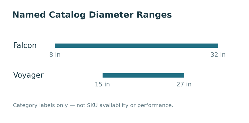 Falcon vs Voyager Propellers for Fixed-Wing UAVs
A fixed-wing propeller shortlist often starts with a diameter limit. The nose, landing gear or pusher installation leaves room for a particular disc, and the buyer searches within…
-
 How to Handle a Warranty Claim on Motors and ESCs
“The motor stopped” describes a symptom. It does not identify the delivered part, show the conditions before the event or explain what happened afterward. That is why a…
-
 CW vs CCW Propellers: Avoiding Mix-Ups in Dealer Kits
A box can contain the right diameter, the right pitch and the right number of propellers, yet still be wrong for the aircraft. The missing check is handedness.…