



4-in-1 vs Single ESC for FPV Builds
A burnt motor channel raises an awkward question: replace one controller, or remove the board that serves all four motors? That service decision is worth making before the frame is wired.
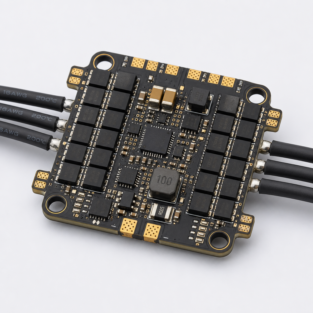
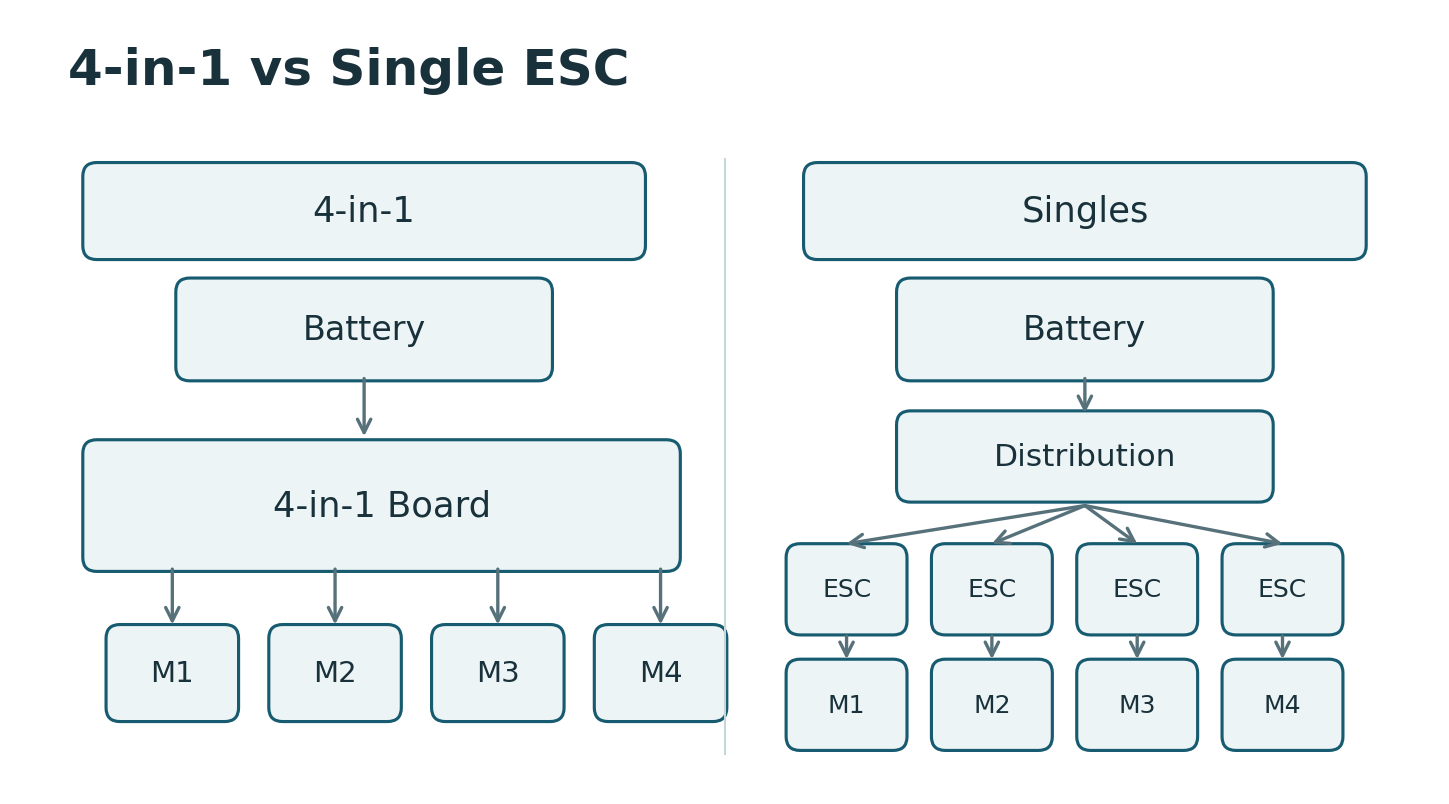
A 4-in-1 ESC puts four motor controllers on one board, usually near the flight controller. Single ESCs distribute the controllers around the airframe. The choice changes stack clearance, cable routing, cooling and the spares you carry. It does not, by itself, decide which aircraft flies better.
For a 4-in-1 vs single ESC comparison, start with the installation and the repair job. Then check the exact products against the electrical load.
4-in-1 vs Single ESC for FPV Builds: Comparison Guide
A compact stack or distributed controllers?
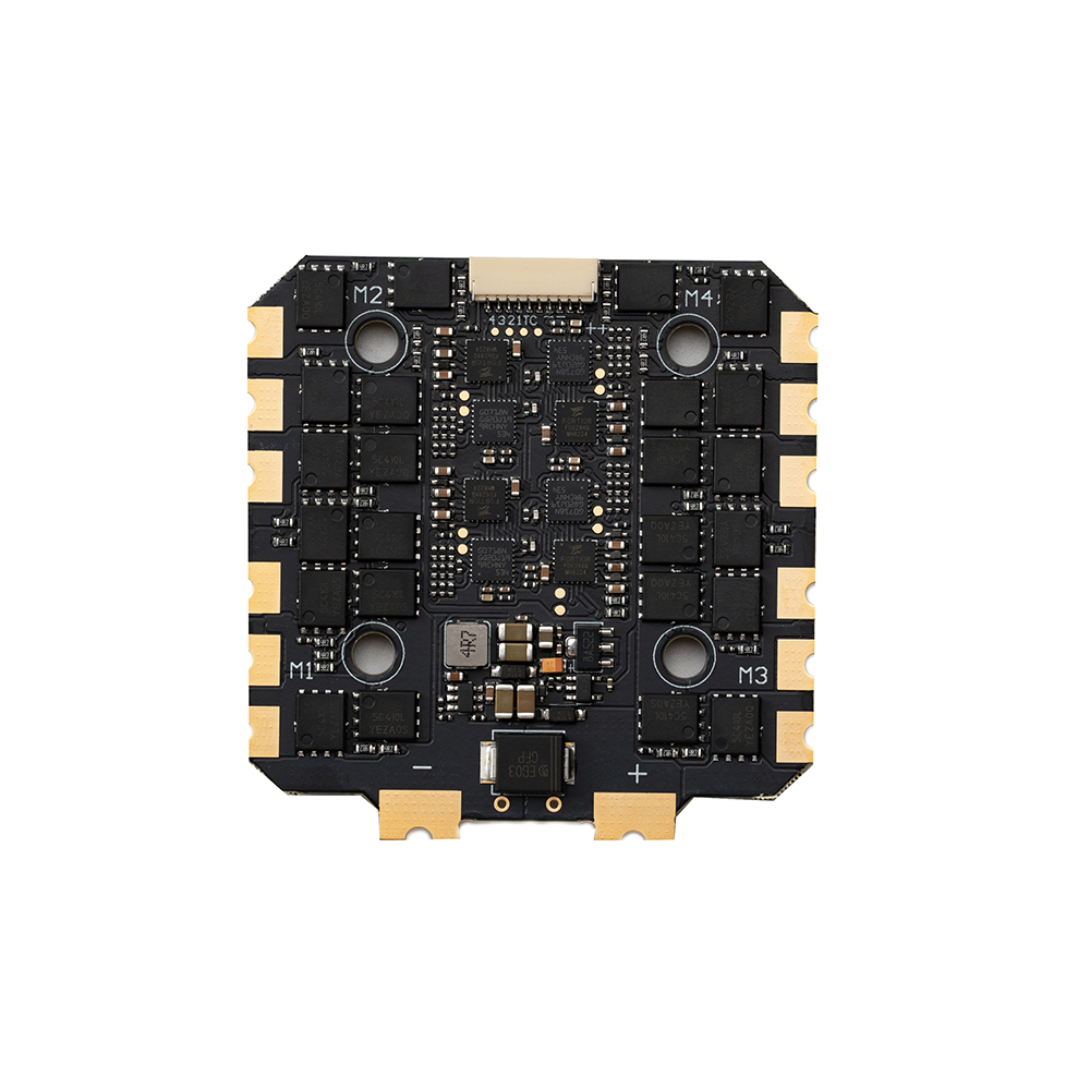
A four-in-one board concentrates the motor power stages in one location. This can reduce separate board mounts and simplify the central assembly. Four motor phase-wire groups still need to reach the board; integration does not eliminate those conductors.
Single ESCs let you place each power stage nearer its motor when the frame permits it. That can shorten the phase-wire run, but battery distribution, signal wiring, mounting and protection must reach each controller. The complete harness may be heavier or lighter depending on the airframe. Compare the installed assembly rather than one bare board with four fully wired units.
The FPV ESC category contains both layouts. Use the topology as a filter, then check voltage, current definitions, dimensions and firmware for the selected SKU.
Trace the power path before comparing dimensions
For a four-in-one installation, check how the battery leads enter the stack, where the specified input capacitor fits and how the motor wires leave the board. The solder joints need clearance from the frame and nearby components. A board can fit its mounting holes and still leave an unworkable cable bend.
With singles, identify the power-distribution point and every branch to an ESC. Review insulation, strain relief, attachment and access for inspection. A convenient arm location is useful only if the controller is mounted and protected according to its instructions.
Signal connections need their own check. A flight-controller harness that fits mechanically is not proof of a matching pinout. Confirm power, ground, motor outputs, sensing and telemetry against both documents before connecting it.
Two catalog examples, with different limits
The PULSAR BL-32 8S 100A 4-in-1 and PULSAR AM32 12S 120A Single illustrate the physical choices. They are different products with different voltage ranges and firmware families, so they are not a controlled performance comparison.
| Published field | BL-32 8S 100A 4-in-1 | AM32 12S 120A Single |
|---|---|---|
| Motor controller layout | Four channels on one board | One motor controller per unit |
| Listed battery range | 3–8S LiPo | 4–12S |
| Continuous-current wording | 100 A × 4 | 120 A |
| Peak-current wording | 110 A, 10 seconds | 130 A, 10 seconds |
| Mechanical information | 30.5 × 30.5 mm mounting pattern, 4 mm holes | Request the drawing; the page labels 71 × 34.5 × 18.2 mm as “Mounting Hole,” which is ambiguous. |
These values come from the listings, not from a new bench test. In particular, “100 A × 4” should not become an unconditional 400 A board rating. The four-in-one page ties its continuous-current statement to forced-air cooling and a temperature condition. The public wording does not fully identify sensor location, ambient temperature or the simultaneous-channel test setup.
Before approval, request the rating definition and thermal conditions for the actual installation. The higher number on a single-controller listing does not establish that four such units are a better propulsion match.
Cooling follows the aircraft, not the product label
The problem starts when a rating established with moving air is applied to a tightly enclosed stack. The four-in-one board may sit beneath a flight controller, video equipment or a cover. Inspect the actual airflow and nearby heat sources rather than assuming forward flight will cool every component adequately.
Singles can offer more freedom over placement, but an arm cover or protective wrapping can restrict cooling too. Distributed mounting is a layout option, not a thermal guarantee.
Evaluate all motor channels under representative duty. A short run on one motor cannot establish the temperature of a four-channel installation. Keep voltage, propellers, ambient conditions, mounting and test duration in the report so the result can be repeated after a component change.
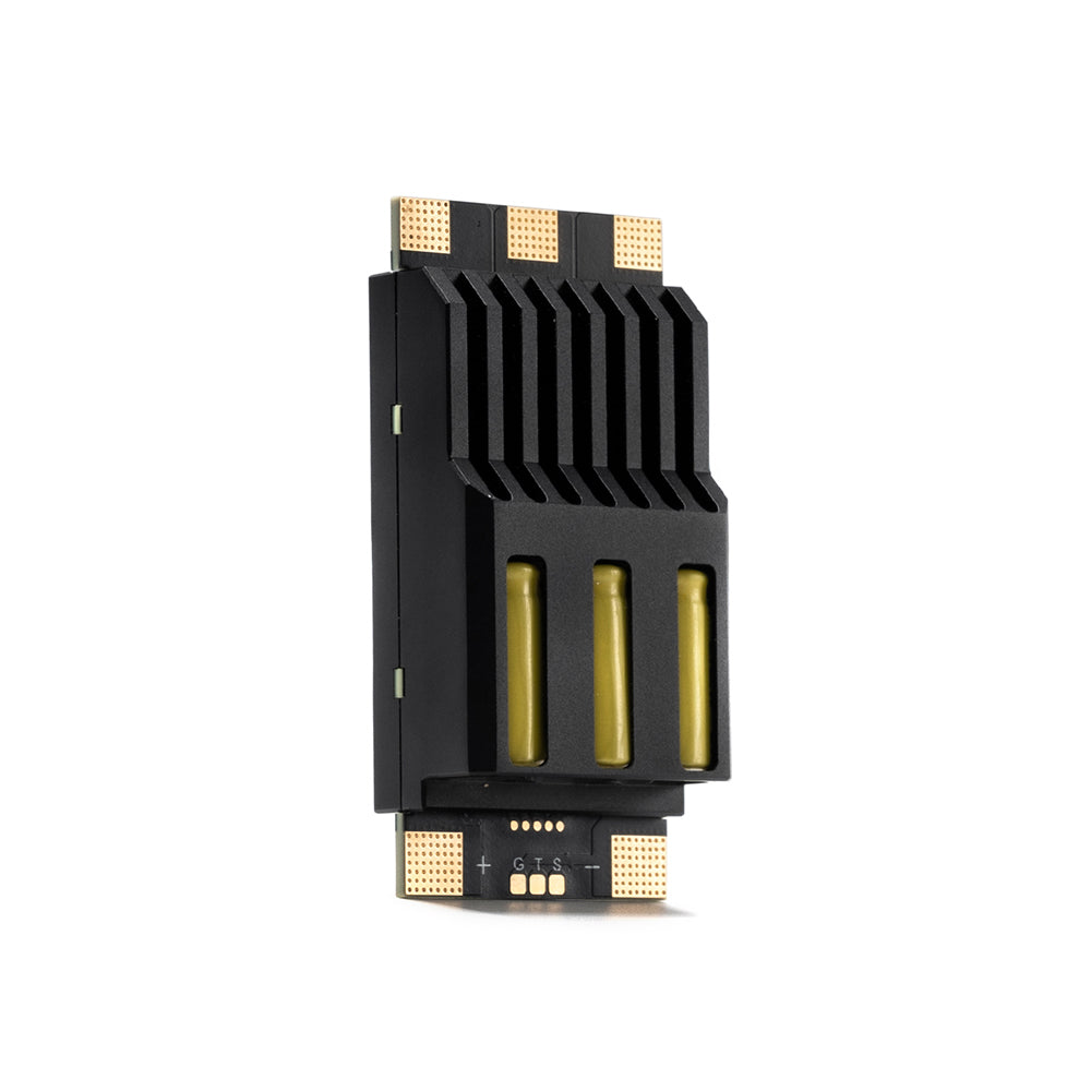
What happens after a damaged channel?
A single ESC can be replaced as a separate service unit, provided the rest of the installation has passed inspection. That can suit an airframe with accessible controllers and a technician who carries compatible singles.
With a four-in-one, the normal field replacement is the complete board unless an approved repair process exists. Access may involve removing the flight-controller stack and disconnecting several motor wire groups. A prepared spare board can still be quick to exchange on a build designed for that job.
Neither layout isolates every fault. A failed motor, damaged cable or power-distribution fault can affect more than the controller you first noticed. Find the cause before installing the spare; otherwise, the replacement may face the same problem.
For a production fleet, record the actual replacement task during sample evaluation. Include access, soldering or connector work, configuration, inspection and the post-repair check. Use that result to compare service effort. There is no verified replacement-time benchmark for these two products in the material reviewed here.
Compare costs at the build and fleet level
Put the complete parts list on each side of the comparison. Include the controllers, power distribution, leads, capacitor, mounting hardware and any protection required by the chosen installation. Count assembly work as well.
Then cost the spare strategy. Four singles can let a fleet stock individual replacements, but they also need controlled firmware and wiring records. A four-in-one spare replaces more hardware at once, while reducing the number of distinct controller units handled during central assembly.
| Build priority | Useful starting point | Check before deciding |
|---|---|---|
| Small central electronics bay | Four-in-one | Board outline, stack height, solder clearance and capacitor location. |
| Accessible distributed service points | Singles | Power-distribution branches, protection and inspection access. |
| Repeated production assembly | Evaluate both on a pilot build | Assembly time, harness variation and configuration control. |
| Field repairs with limited tools | Evaluate the complete replacement task | Spare preparation, access and the work required after replacement. |
Do not compare purchase prices as though the voltage and current envelopes were identical. Use candidates that first meet the motor–propeller duty, then compare the cost of keeping the aircraft in service.
Before you release the layout
Resolve the physical arrangement on the actual frame. Check the wiring diagram, connector pinout, cooling requirements and permitted mounting method. Confirm firmware identification and the configuration process for replacement units.
Choose a four-in-one when the central installation works and its board-level replacement suits the service plan. Choose singles when distributed placement and individual replacement justify the additional harness and mounting work. Either choice needs electrical and thermal validation with the proposed motors and propellers.
For a build review, send the frame and propulsion details, including pack voltage, motor and propeller, available stack space, cooling arrangement and spare strategy. Ask for the wiring and dimensional documents for the exact ESC revision.
FAQ
Can I replace one channel on a four-in-one ESC?
Treat the complete board as the service replacement unless the manufacturer provides an approved repair route. Four channels on one PCB are not four removable modules. Before fitting the replacement, inspect the associated motor and wiring and determine the fault cause. A new board should not be used to test an unresolved short circuit.
Is a 100 A four-in-one the same as four 100 A singles?
Not automatically. Compare the current definitions, cooling conditions, voltage range and simultaneous loading limits. The four-in-one shares a physical board and installation environment. Four singles have a different harness and thermal arrangement. Matching headline amp figures does not prove that the assemblies support the same installed duty.
Will a plug-and-play flight-controller cable work with any board?
No. Check the pin assignments and electrical functions on both products. Matching connector shape or pin count is insufficient. Keep the approved harness drawing with the build record so a replacement cable or ESC revision does not silently change the power, signal or telemetry connections.
Do single ESCs always reduce aircraft weight?
No. Include four controllers, power distribution, wires, mounting and protection before comparing mass with a four-in-one installation. Motor phase-wire length and battery branch routing depend on the frame. Weigh the complete candidate assemblies on the same basis rather than combining bare-board figures with wired-unit figures.
Does a four-in-one need a capacitor?
Follow the selected controller’s installation instructions. The website FAQ explains that an input capacitor helps suppress power-bus transients associated with motor braking. Its required type, rating and placement are product-specific. The conceptual layout in this article omits capacitors and must not be used as a complete wiring diagram.
Can I change ESC firmware while changing the layout?
It creates another variable to validate. The BL-32 and AM32 examples here use different firmware families as well as different hardware layouts. Check configuration tools, motor protocol, telemetry and replacement settings for the chosen product. Do not attribute a change in behavior to topology when firmware or the electrical operating point changed too.
Related UAV resources: FPV ESC products, drone propulsion products, and contact REACHSKY.
Related articles
-
 Motor Desync High Current: Causes and Fixes
Why a motor loses commutation exactly when current climbs, the six causes in the order worth checking, and a bench routine that makes desync repeatable.
-
 FPV Motor Series Explained: BSC, CM, FS and KONKER
A series name helps you find a motor. It does not finish the selection. ??inematic??is not a payload rating, ??reestyle??is not a battery specification, and ??asic??does not tell…
-
 Drone Motor Bearing Maintenance and Replacement Intervals
A motor that sounds different after a prop strike needs an inspection, even if it is far from its planned service date. A motor that sounds unchanged still…
-
 Heavy-Lift Drone Motor Selection: Payload, Thrust and Redundancy
A step-by-step heavy-lift drone motor selection method: payload to all-up weight, thrust per arm, redundancy reserve, then a datasheet check on the AM110.