


Heavy Lift Power Combo: How to Choose One for a New Airframe
Payload and hover time first, then thrust per arm, prop diameter, KV ceiling, ESC current and pack count. A worked 50 kg hexacopter example.
TL;DR
- A heavy lift power combo is sized from three inputs fixed before you open a catalogue: takeoff mass, required hover time, and site density altitude. Prop diameter, KV, ESC current and pack count follow from those three.
- Prop diameter sets an RPM ceiling through tip speed, and bus voltage turns that ceiling into a KV limit. A 4.5 KV motor is a high-voltage motor: on an 88.8 V bus it turns about 400 rpm, on 400 V it turns 1,800.
- Extra packs stop paying early. A second pack adds 10.6 minutes of hover, a third adds 6.3, and a fourth adds 3.8 while adding 24.4 kg the airframe still carries.
A heavy lift power combo is a matched set of motor, propeller, ESC and pack, and the dependable way to choose one is to work backwards from what the airframe has to do. Teams that start from a motor catalogue finish with a set that hovers far below its rated thrust or draws more current than the ESC margin allows. This guide runs the sequence on a 50 kg payload hexacopter and shows the arithmetic at every step.
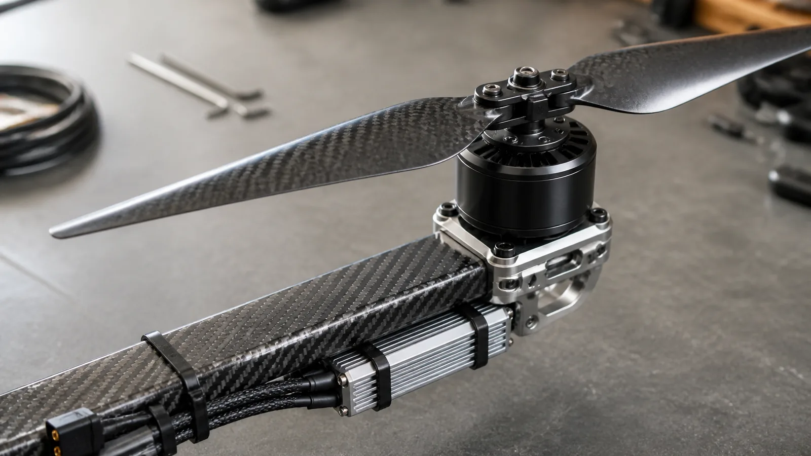
A propulsion set is judged installed, not on a bench: arm stiffness, cable routing and prop clearance all change the number the thrust table gives you.
Start from payload and hover time, not from a motor catalogue
Payload and hover time constrain everything else, and both have to be written as site conditions rather than brochure conditions. A 50 kg payload is not a requirement until you say whether it includes the release mechanism.
- Payload covers what the aircraft carries for the mission and nothing it needs to fly: camera, tank, spray boom, cargo box, release servo. Battery, harness and avionics sit in the structure line.
- Hover time runs from a stable hover to the point where you must start descent with reserve still in the pack. Usable energy is typically 80% of nameplate for a pack you keep for several hundred cycles.
- Site conditions mean density altitude at the hottest hour you actually fly. A set holding 46 kgf per arm at sea level on a 15 °C morning will not hold it at 2,000 m on a 35 °C afternoon.
Write these four lines down before the first supplier email: payload in kg, hover time in minutes, density altitude in metres, design bus voltage. A supplier who quotes a combo without asking for them is quoting a catalogue page.
The work-back sequence in six steps
The sequence converts one unknown into one number at a time, and each number is small enough to put in an email. Run it in this order; out of order is how a project picks a propeller the arms cannot clear.
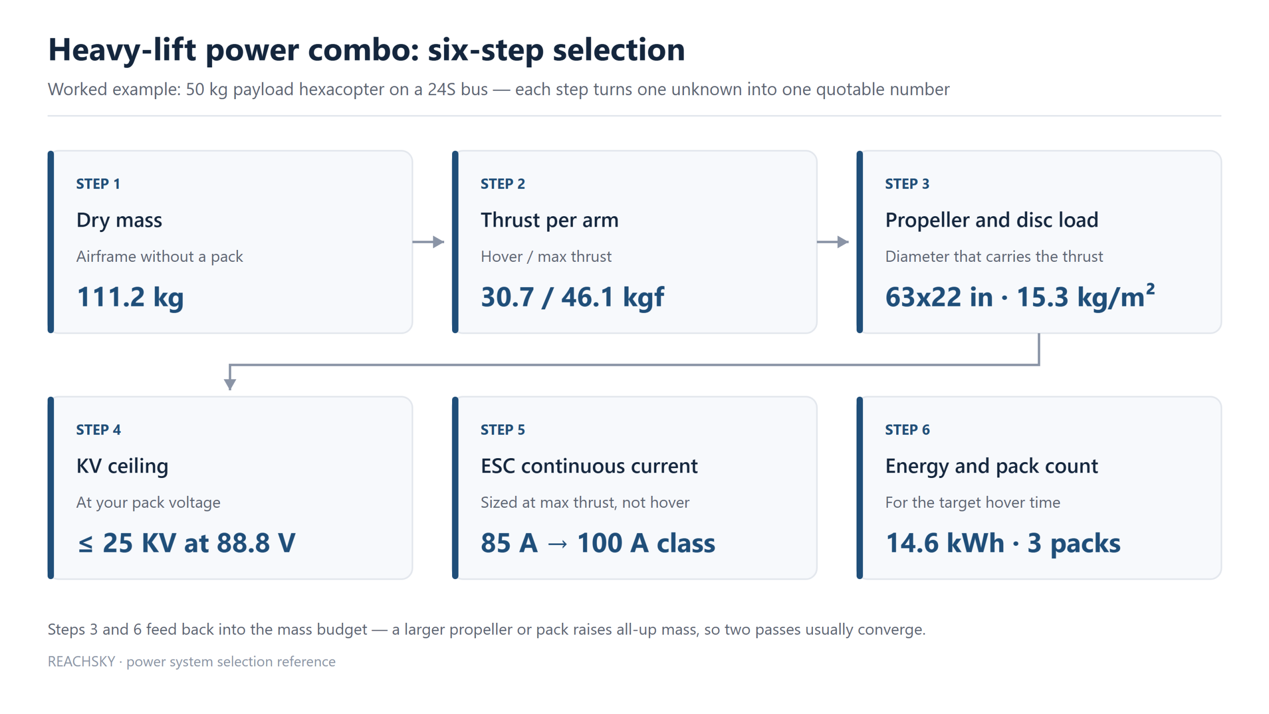
The six steps in order, with the worked-example values carried through each box; steps 3 and 6 are where most first drafts get their numbers wrong.
Steps 3 and 6 feed back into the mass budget, which makes the sequence a loop: a larger propeller raises arm mass and span, a larger pack raises all-up mass, and both push thrust per arm up again. Two passes usually converge.
Worked example: a 50 kg payload hexacopter on a 24S bus
The airframe is a six-arm single-rotor layout on a 24S bus, chosen because 24S is the top of the range most integrators can charge on one bench charger. Every assumption is stated, so you can replace it with a datasheet value.
Step 1: build the mass budget before you size anything
The pack line is the variable. Replace the propulsion line first: a 0.5 kg error per arm moves the whole answer by 3 kg.
Step 2: convert mass into thrust per arm
Hover thrust per arm is all-up mass divided by arm count; max thrust is that number times the thrust-to-weight ratio you design for. At 184.4 kg takeoff mass, hover is 30.7 kgf per arm, and a ratio of 1.5 gives 46.1 kgf.
Why 1.5 and not 1.2: gust response and yaw authority draw on the same margin; losing one arm on a hexacopter leaves five, so the aircraft needs reserve to descend rather than fall; density altitude eats the top of the curve first.
Check the requirement at max continuous thrust, not burst. A ten-second rating will not hold a 35 minute hover. How to read those rows is in our guide to heavy-lift motor selection.
Step 3: match propeller diameter to disc loading and tip clearance
Disc loading is all-up mass divided by total disc area, and it predicts hover power better than any other single figure. A 63×22 in propeller sweeps 2.01 m² per rotor, so six rotors give 12.07 m² and the airframe sits at 15.3 kg/m².
Cargo multirotors live between 10 and 16 kg/m². Above that band induced power climbs steeply and hover time collapses faster than the mass budget predicts. A 63 in propeller is the smallest that keeps this airframe inside the band, which is why arm geometry grows with it: adjacent hubs need at least 1.15 propeller diameters between centres, so a 1.60 m propeller needs 1.84 m, and the tip circle comes out at 5.28 m across.
Tip speed caps the rest. At 0.55 Mach the tip of a 1.60 m blade moves at about 189 m/s, which limits the rotor to roughly 2,256 rpm. That number decides the KV discussion below, and it is why a bigger propeller is not automatically better: past the tip-speed limit, added diameter buys noise and vibration instead of thrust.
Step 4: size the pack from energy, then count packs
Hover power comes from momentum theory with a figure of merit for real rotors: P = (mg)^1.5 / (√(2ρA) × FM). At 184.4 kg, 12.07 m² of disc and a figure of merit of 0.72, that is 19.65 kW at the rotor, or 3.28 kW per arm.
- Usable energy for 35 minutes: 19.65 kW × 0.596 h = 11.7 kWh.
- Installed energy at 80% usable: 14.6 kWh.
- A 24S 55Ah pack holds 88.8 V × 55 Ah = 4.88 kWh, so the requirement is 3.0 packs.
Three packs put takeoff mass at 184.4 kg and hover time at 35.8 minutes. The interesting part is what a fourth pack does.
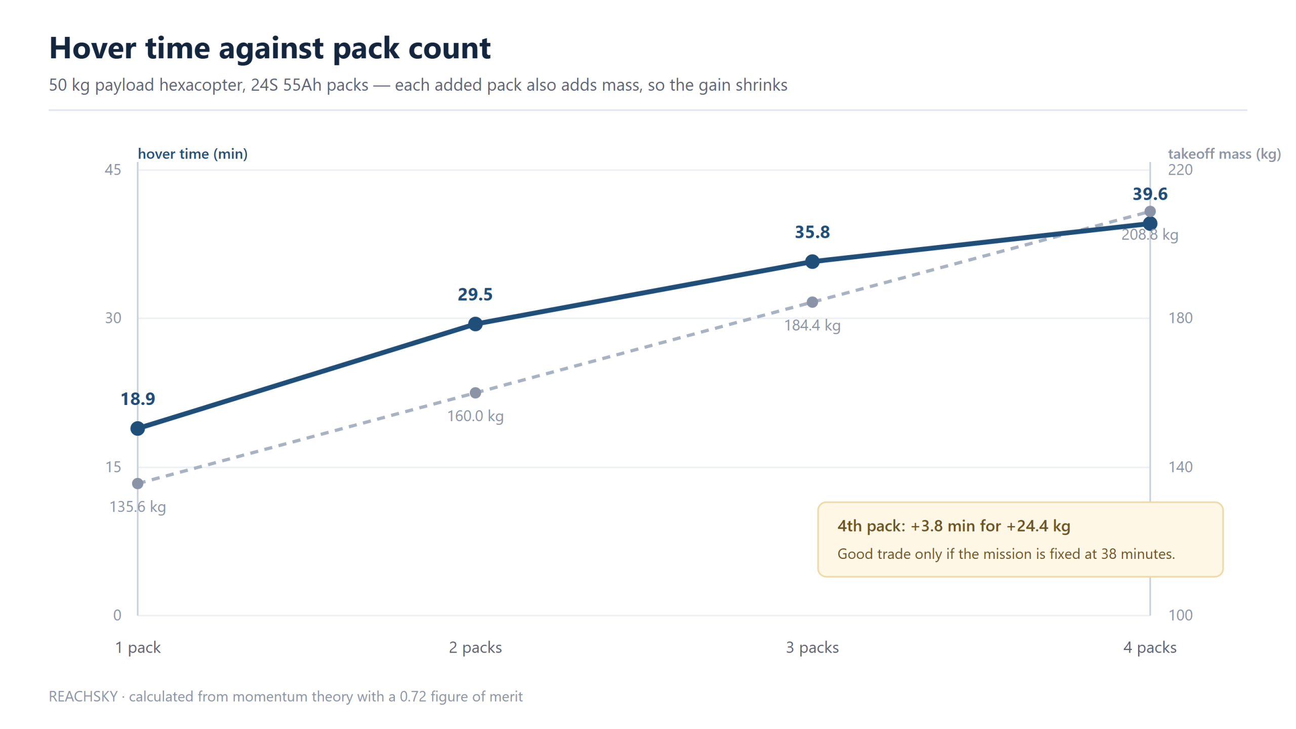
Each added 24S 55Ah pack contributes less hover time than the one before it, because the pack also raises the thrust the other packs have to support.
The fourth pack buys 3.8 minutes and costs 24.4 kg of mass budget. If the mission can trade that mass for payload, it is a bad trade; if the mission is fixed at 50 kg and 38 minutes, it is the only option.
Step 5: set ESC current from the max-thrust point
At max thrust, per-arm power rises faster than thrust, roughly as the 1.5 power. Scaling 3.28 kW by 1.5^1.5 gives 6.02 kW per arm, and at 88.8 V that is 67.7 A. Add 25% and the continuous rating lands at 85 A, which puts the arm in the 100 A class.
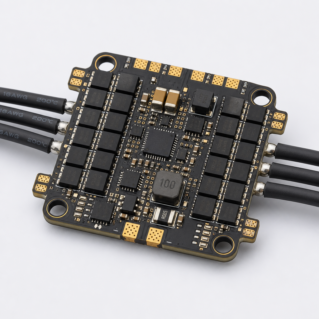
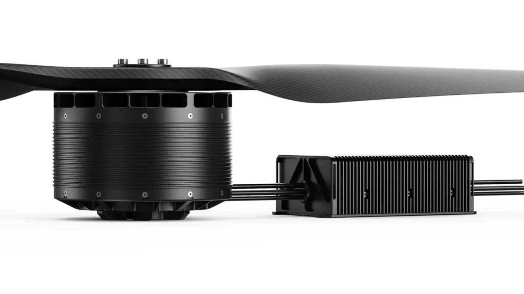
Size at the low end of the voltage window: 88.8 V nominal becomes 86.4 V near the end of discharge. And an ESC inside an arm tube runs hotter than the same ESC on an open bench, as in the image above — a real derating condition, not a rounding error.
How do propeller diameter and motor KV couple?
Propeller diameter sets an RPM ceiling through tip speed, and bus voltage converts that ceiling into a KV limit, so neither number means anything alone. The ceiling is RPM = (tip speed × 60) / (π × diameter); the KV limit is that RPM divided by bus voltage.
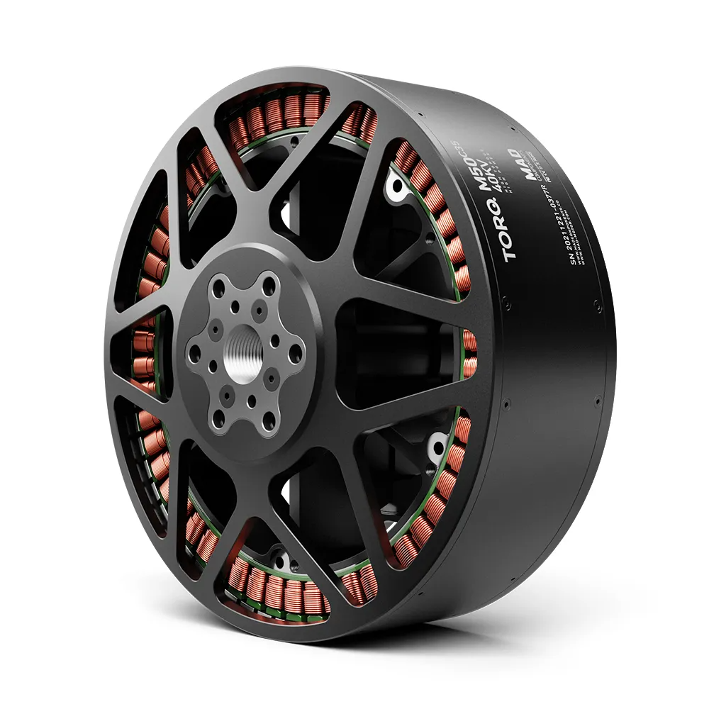
Read the last row against a real product. The AM160 4.5KV Heavy-Lift Power System Kit pairs a 4.5 KV motor with a 78×30 in propeller. At 400 V, 4.5 KV gives 1,800 rpm no-load and the 78×30 tip-speed ceiling is about 1,822 rpm: the pairing sits where it should. On an 88.8 V bus the same motor turns 400 rpm, and a 1.98 m propeller at 400 rpm produces almost nothing.
That is the trap in shopping by KV. A 25 KV motor and a 4.5 KV motor are not two grades of the same thing, and comparing them without a bus voltage is comparing nothing. Once the ceiling check passes, the choice comes from the thrust table at your voltage, because two motors with the same KV can differ by 20% in thrust at the same current depending on stator size, magnet grade and winding resistance.
For the worked example the ceiling at 88.8 V is 25.4, so the shortlist sits between roughly 20 and 30 KV. Higher wastes the propeller in tip loss and noise; much lower needs a bigger propeller or a higher bus than the arm allows. A combo matched at the factory skips this negotiation, which is the case for the HB60-63×22 Drone Power Combo and the rest of the heavy-lift power system kit and drone arm set range in that class.
How much ESC headroom should you carry?
Carry 25% over the max-thrust current measured at the lowest pack voltage, bought as a continuous rating rather than a burst rating. It covers four losses that appear at once on a hot day.
- Voltage sag. Current rises as the pack drains, so the worst case is the last minute of a hover, not the first.
- Thermal stacking. An ESC in an arm tube, next to a motor heating the same carbon structure, runs hotter than the datasheet bench condition.
- Altitude. Thin air cools the heat sink least at exactly the density altitude that already cost you thrust margin.
- Connector and harness loss. Long arm runs add resistance that shows up as heat at the plugs, not at the ESC.
A 4-in-1 ESC changes the calculation rather than removing it: one board rated at 4 × 60 A continuous is not four 60 A units, because it shares one heat path and one capacitor bank.
Battery series count, capacity and C-rate in one pass
Series count comes from bus voltage, capacity from energy, and C-rate from current, and all three must agree before a pack is ordered. For the worked example the bus is 24S: 88.8 V nominal, 100.8 V full charge. Capacity comes from energy — 14.6 kWh across three packs is 4.88 kWh each, or 55 Ah at 88.8 V.
C-rate catches mistakes. Hover current is 19.65 kW ÷ 88.8 V = 221 A total, split across three packs, which is 74 A per pack and 1.34C on a 55 Ah pack. The max-thrust case is tighter: 221 A × 1.5^1.5 is about 407 A, or 136 A per pack and 2.47C, which has to sit inside the pack’s continuous rating with margin.
Two rules keep parallel strings out of trouble. Use identical packs of the same age and state of charge, and never mix a fresh pack with one that has 80 cycles on it, because the fresh pack carries more load and ages faster. The relationships are worked through in drone battery selection.
Higher voltage is not free. Raising the bus halves current for the same power and thins the harness, but it moves the ESC into another voltage class, doubles the series string that must stay balanced, and pushes the KV limit where fewer motors exist. The right bus is the lowest one that keeps current inside a sensible connector and cable size.
Arm weight, tip clearance and centre of gravity
Arm mass hurts more than its kilogram count suggests, because it sits at the largest radius. Adding 0.5 kg per arm at a 1.84 m hub radius adds about 10 kg·m² of yaw inertia across six arms, which shows up as slower yaw response and gain hunting, not as a weight problem on the scale.
- Tip clearance. Adjacent hubs need at least 1.15 propeller diameters between centres. Below that, blade flex brings tips close enough to interact, and the vibration shows in the gyro before it shows in the frame.
- Ground clearance. With the gear compressed under a full pack, the lowest tip should still clear the ground by about 100 mm. Measure it loaded, not empty.
- Centre of gravity. Keep the CoG within about 20 mm of the geometric centre, and use pack position as the trim tool: moving a 24.4 kg pack 100 mm shifts a 184 kg aircraft by roughly 13 mm.
Cable routing belongs to the same decision. Phase wires should leave the arm root with a service loop and strain relief, run outside the propeller disc and stay clear of the ESC heat sink. A wire that touches a spinning hub once fails at the connector a few flights later, and the failure looks like an ESC problem. Mounting hardware is where new airframes lose the most time: bolt circle, tube diameter and clamp width must match the arm set before the order, because a 2 mm mismatch is a new arm, not a reamed hole.
From selected combo to a signed order
A first airframe usually needs about twelve weeks from a fixed requirement to a production order, and the week that gets skipped is the bench week. Three throttle points – 50%, 75% and full – catch a mismatched KV, a propeller that stalls earlier than the table suggests, and an ESC already hot at part throttle. If measured thrust sits more than 5% below the published figure, re-check bus voltage and the propeller part number before the first hover.
Lead times by order track (stock, sample, OEM) are covered in drone parts lead times. The cost trade between a matched kit and separate parts is in power system kit vs separate parts: the kit price buys matching and documentation, the separate-parts route buys flexibility at the cost of your own bench time.
常见问题
What is a heavy lift power combo? A motor, propeller, ESC and pack selected together as one matched set, usually sold as an arm set or kit. The parts are sized from the same mass budget and bus voltage, so thrust, current and hover time agree before the first flight.
How do I calculate thrust per arm for a heavy-lift drone? Divide all-up mass by arm count for hover thrust, then multiply by 1.4 to 1.6 for the max-thrust target. A 184 kg hexacopter needs 30.7 kgf per arm to hover and about 46 kgf to hold a 1.5 ratio.
Should I buy a matched combo or separate motor, prop and ESC? Buy the combo when the airframe is close to an existing design and you want matching risk removed. Buy separate parts while propeller diameter or bus voltage is still moving, because a locked KV and prop pairing cannot be renegotiated after delivery without replacing the arm.
Can I run a 4.5 KV motor on a 24S battery? No. At 88.8 V it turns about 400 rpm, far below what a 78 in propeller needs. That winding belongs on a high-voltage bus, where 4.5 KV × 400 V gives 1,800 rpm and tip speed lands near 187 m/s.
How many battery packs does a 50 kg payload drone need? Three 24S 55Ah packs for a 35 minute hover at 15.3 kg/m², giving 35.8 minutes at 184.4 kg takeoff mass. A fourth pack adds 3.8 minutes but also 24.4 kg, so it pays only if the mission cannot trade mass for time.
What ESC size do I need for 30 kgf per arm at hover? About 100 A continuous. Hover draws roughly 37 A per arm at 88.8 V, max thrust about 68 A, and 25% margin lands at 85 A, which rounds up to the 100 A class. Size at the low end of the voltage window.
Choosing a heavy lift power combo is a sequence, not a shopping list
A heavy lift power combo that works on a new airframe is the output of six numbers, not the input to them: dry mass, thrust per arm, disc loading, KV ceiling, ESC current and installed energy. Run them in order, run the mass loop twice, and the shortlist stops being a matter of opinion. The two failure modes to watch are a KV chosen without a bus voltage and a pack count chosen without re-running the thrust requirement, because both look fine on paper and both show up as heat on the third flight.
Send your mass budget, hover time and site conditions and we will return a matched shortlist with the thrust table rows that apply.
Propeller performance references come from the UIUC Propeller Database; for the regulatory context of larger platforms, see EASA’s drone pages.
All products are supplied for civil end use only.
About the author. REACHSKY Engineering Team, Changsha, Hunan. Twelve years supplying UAV propulsion components, with in-house motor and arm design, ISO 9001 process control, and bench testing for thrust, current, input power and efficiency.
Last updated: 2026-10-31
相关文章
-
 Integrated FOC Arm Sets: Why KV and Prop Size Are Fixed
A replacement motor bolts onto the arm. The propeller clears the frame. The connector fits. None of those checks confirms that the original controller setup still applies. An…
-
 Power System Kit vs Buying Parts Separately
A matched kit trades a higher unit price for one shipment, one owner of the match and less rework. How the four purchase dimensions actually compare.